OpenSCAD教程
Doing math calculations in OpenSCAD
::在OpenSCAD中进行数学计算
So far you have learned that OpenSCAD variables can hold only one value throughout the execution of a script, the last value that has been assigned to them. You have also learned that a common use of OpenSCAD variables is to provide parameterization of your models. In this case every parameterized model would have a few independent variables, whose values you can change to tune that model. These variables are usually directly assigned a value as in the following examples.
::到目前为止,你已经知道OpenSCAD变量只能在脚本执行过程中保留一个值,即被赋予的最后一个值.你也已经知道OpenSCAD变量的常用是为你的模型提供参数化.在这种情况下,每个参数化的模型都会有几个独立变量,你可以改变它们的值来调整该模型.这些变量通常直接被赋予一个值,如下面的例子.
… wheel_diameter = 12; … body_length = 70; … wheelbase = 40; … // etc. … |
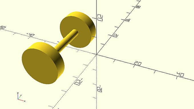
Another thing that you have seen a few times already, but which has not been mentioned explicitly is the ability to perform mathematical operations using variables and hard-coded values in your script. One example of this is in implementing the car's wheelbase. Recall that the car's axles and wheels were translated along the X axis and away from the origin by half the value of the wheelbase. Since in this case the wheelbase is a variable that has already been defined in your script, you can calculate the amount of units by dividing the wheelbase variable by two. A similar thing was done with the track variable to place the left and right wheels of the car. Recall that the left and right wheels were translated along the Y axis and away from the origin by half the value of the track.
::另外一个你已经看过几次,但没有明确提到的东西是使用变量和硬编码值在脚本中执行数学运算的能力.其中一个例子是实现汽车的轴距.请记住,汽车的轴和轮子沿X轴转移,并从原点远离轴距的一半.由于在这种情况下轴距是一个已经定义在脚本中的变量,你可以通过将轴距变量除以2来计算单位数量.类似的事情是用轨道变量来放置汽车的左和右轮.请记住,左和右轮子沿Y轴转移,并从原点远离轨道的一半.
|
axle_with_wheelset.scad
use <vehicle_parts.scad>
$fa = 1;
$fs = 0.4;

wheelbase = 40;
track = 35;

translate([-wheelbase/2, track/2])
    simple_wheel();
translate([-wheelbase/2, -track/2])
    simple_wheel();
translate([-wheelbase/2, 0, 0])
    axle(track=track);
|
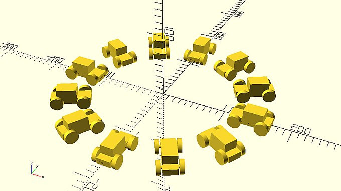
Addition, subtraction, multiplication and division are represented in OpenSCAD with the signs +, -, * and /. Apart from these fundamental operations, there are also a number of additional mathematical operations that can be useful when building more complex models. Two examples of this are the cosine and sine functions that you used to define a circular pattern of cars. Specifically, you used the cosine and sine functions to transform the polar coordinates of each car into Cartesian coordinates in order to translate it in its proper position. You can find all available math functions briefly listed in the cheat sheet.
::添加,减去,乘法和除法在OpenSCAD中用符号+, -, *和/表示.除了这些基本操作外,还有一些额外的数学操作,在构建更复杂的模型时可能有用.其中两个例子是你用来定义汽车圆形图案的等号函数和正号函数.具体来说,你使用等号函数将每个汽车的极坐标转换为笛卡尔坐标,以便将其转换为适当的位置.你可以在作弊表中找到所有可用的数学函数.
|
circular_pattern_of_cars.scad
…
r = 140; // pattern radius
n = 12; // number of cars
step = 360/n;
for (i=[0:step:359]) {
    angle = i;
    dx = r*cos(angle);
    dy = r*sin(angle);
    translate([dx,dy,0])
        rotate([0,0,angle])
        car();
}
…
|
In the above case you are not only using available mathematical operations in your script, but you are also defining two additional variables dx and dy to store the result of your calculations in order to increase the readability of your script. This is something that could also be done in your car models. Take for example the following car model.
::在上述情况下,你不仅在脚本中使用可用的数学运算,还定义了两个额外的变量dx和dy来存储你的计算结果,以提高脚本的可读性.这也可以在你的汽车模型中做.例如下面的汽车模型.
|
car.scad
use <vehicle_parts.scad>
$fa = 1;
$fs = 0.4;

wheelbase = 40;
track = 35;

// Body
body();
// Front left wheel
translate([-wheelbase/2,-track/2,0])
    simple_wheel();
 // Front right wheel
translate([-wheelbase/2,track/2,0])
    simple_wheel();
// Rear left wheel
translate([wheelbase/2,-track/2,0])
    simple_wheel();
// Rear right wheel
translate([wheelbase/2,track/2,0])
    simple_wheel();
// Front axle
translate([-wheelbase/2,0,0])
    axle(track=track);
// Rear axle
translate([wheelbase/2,0,0])
    axle(track=track);
|
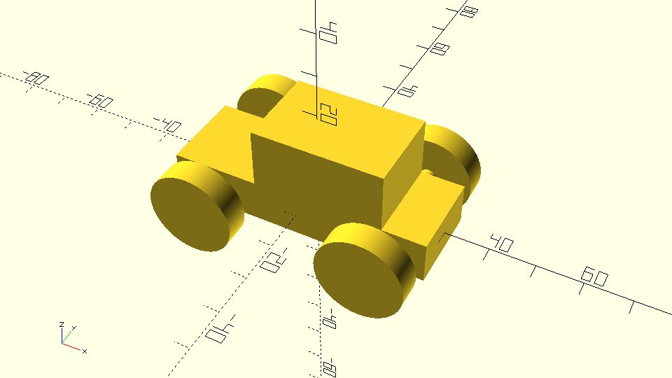
In the above model, mathematical operations are used to calculate the required amount of translation for each wheel and axle along the X and Y axis.
::在上述模型中,数学运算用于计算 X 和 Y 轴沿各轮和轴所需的转移量.
| Modify the above script in order to improve its readability and avoid repeating the same mathematical operations multiple times. To do so you should introduce two new variables named half_wheelbase and half_track. Use the corresponding mathematical calculation to set these variables equal to half the value of the wheelbase and the track variables accordingly. Replace the repeating mathematical operations in the translation commands with the use of these two variables. |
|
car_with_additional_variables.scad
use <vehicle_parts.scad>
$fa = 1;
$fs = 0.4;

wheelbase = 40;
track = 35;

half_wheelbase = wheelbase/2;
half_track = track/2;

// Body
body();
// Front left wheel
translate([-half_wheelbase,-half_track,0])
    simple_wheel();
 // Front right wheel
translate([-half_wheelbase,half_track,0])
    simple_wheel();
// Rear left wheel
translate([half_wheelbase,-half_track,0])
    simple_wheel();
// Rear right wheel
translate([half_wheelbase,half_track,0])
    simple_wheel();
// Front axle
translate([-half_wheelbase,0,0])
    axle(track=track);
// Rear axle
translate([half_wheelbase,0,0])
    axle(track=track);
|

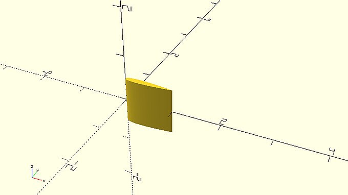
Creating any 2D object with the polygon primitive
::使用多边形原始创建任何 2D 对象
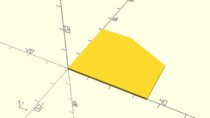
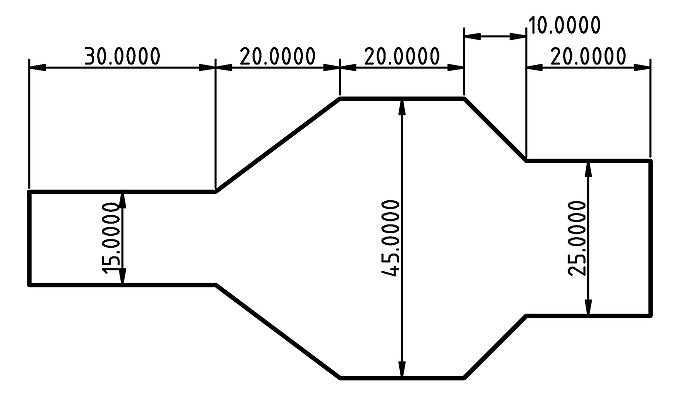
Aside from the circle and square 2D primitives, there is another primitive that lets you design practically any 2D object. This is the polygon primitive, which lets you define 2D objects by providing a list that contains the coordinates of their points. Let’s say you want to design the following 2D part.
::除了圆和方二维原始,还有一个原始,它允许你设计任何二维对象.这是多边形原始,它允许你通过提供包含它们点的坐标的列表来定义二维对象.假设你想设计下面的二维部分.
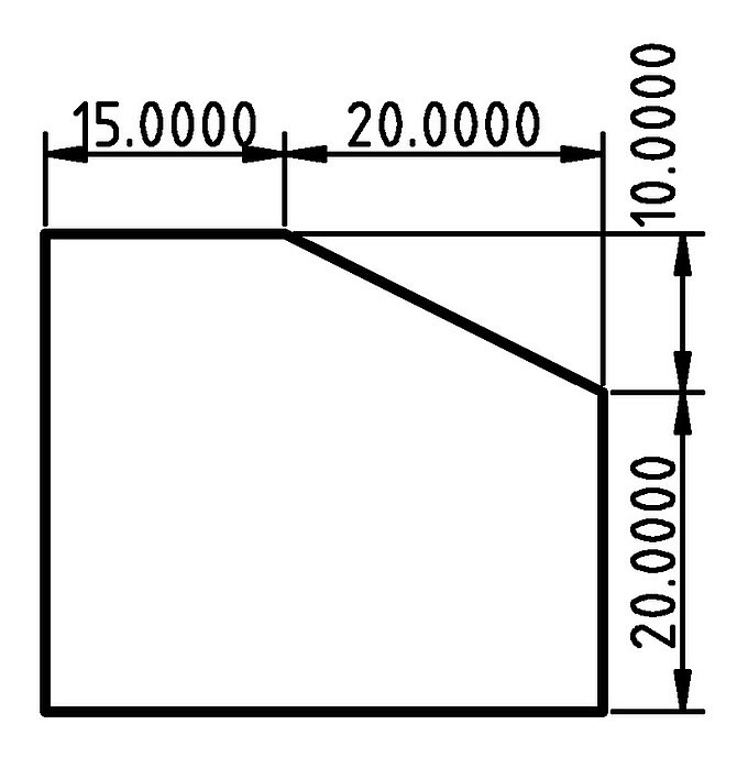
One way to go about designing this part without using the polygon primitive would be to start from a square that corresponds to the outer dimensions of this part and then subtract a properly rotated and translated square from its top right corner. Calculating the proper angle of rotation and amount of translation would be a time-consuming task. Additionally, following this strategy for a more complex object wouldn’t be possible. Instead, you can create this object using the polygon primitive in the following way.
::设计这个部分而不使用多边形原始的方法之一是从一个与这个部分的外接尺寸相对应的正方形开始,然后从它的右上角减去一个正确旋转和翻译的正方形.计算适当的旋转角度和翻译量将是一个耗时的任务.此外,对于更复杂的对象,遵循这种策略是不可能的.相反,你可以用以下方式创建这个对象,使用多边形原始.
|
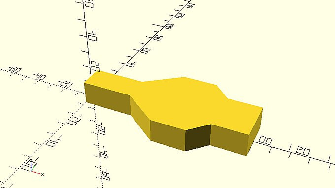
profile_1_polygon.scad
p0 = [0, 0]; p1 = [0, 30]; p2 = [15, 30]; p3 = [35, 20]; p4 = [35, 0]; points = [p0, p1, p2, p3, p4]; polygon(points); |
There are a few things you should notice regarding the use of the polygon primitive. The polygon primitive uses a list of points as inputs. The points, or vertices, are represented using pairs of X and Y coordinates, and are provided in order. When defining the list, you may start with any vertex you like and you can traverse them in either a clockwise or counterclockwise order. In the example above, the first vertex is at the origin (0,0), while the remaining vertices are listed in a clockwise direction. All vertices (pairs of X and Y coordinates) p0, p1, …, p4 are placed inside a list named points. This list is then passed to the polygon command to create the corresponding object.
::关于使用多边形原始的,你应该注意到一些事情.多边形原始使用一个列表的点作为输入.点,或顶点,是用X和Y坐标的对表示,并提供了顺序.在定义列表时,你可以从任何顶点开始,你可以在时钟针方向或反时钟方向顺序穿过它们.在上面的例子中,第一个顶点在原点 (0,0),而剩余的顶点是以时钟方向列出的.所有顶点 (X和Y坐标的对) p0,p1, ...,p4都放置在一个名为点的列表内.然后将其传递给多边形命令列表以创建相应的对象.
Whether a variable has only a single value or it’s a list of values, you can print its content on the console using the echo command.
::无论一个变量只有一项值还是它是一个值列表,
… echo(points); … |
The output in the console is: [[0, 0], [0, 30], [15, 30], [35, 20], [35, 0]]
::控制台的输出是: [[0, 0], [0, 30], [15, 30], [35, 20], [35, 0]]
Naming each point separately (p0, p1, …) is not required but it’s recommended to better keep track of your design. You could also directly define the list of points to be passed to the polygon command.
::没有必要单独命名每个点 (p0,p1,...) 但建议更好地跟踪您的设计.您也可以直接定义要传递给多边形命令的点列表.
… points = [[0, 0], [0, 30], [15, 30], [35, 20], [35, 0]]; … |
Moreover, you don’t even have to define a variable to store the list of points. You can directly define the list of points when calling the polygon command.
::您甚至不需要定义一个变量来存储点列表. 您可以在调用多边形命令时直接定义点列表.
… polygon([[0, 0], [0, 30], [15, 30], [35, 20], [35, 0]]); … |
The above practices are not recommended. Instead the use of additional variables as in the first example is encouraged in order to make your scripts more readable and extendable.
::建议使用前面的方法, 否则会像第一个例子中一样使用额外的变量,
You could also parameterize the definition of the points’ coordinates according to the given dimensions, which will give you the ability to rapidly modify the dimensions of your object. This can be achieved by introducing one variable for each given dimension and by defining the coordinates of the points using appropriate mathematical expressions.
::您还可以根据给定的维度对点坐标的定义进行参数化,这将使您能够快速修改对象的维度.这可以通过为每个给定的维度引入一个变量并使用适当的数学表达式定义点的坐标来实现.
|
profile_1_polygon_parametric.scad
// Given dimensions d1 = 15; d2 = 20; h1 = 20; h2 = 10; // Points p0 = [0, 0]; p1 = [0, h1 + h2]; p2 = [d1, h1 + h2]; p3 = [d1 + d2, h1]; p4 = [d1 + d2, 0]; points = [p0, p1, p2, p3, p4]; // Polygon polygon(points); |
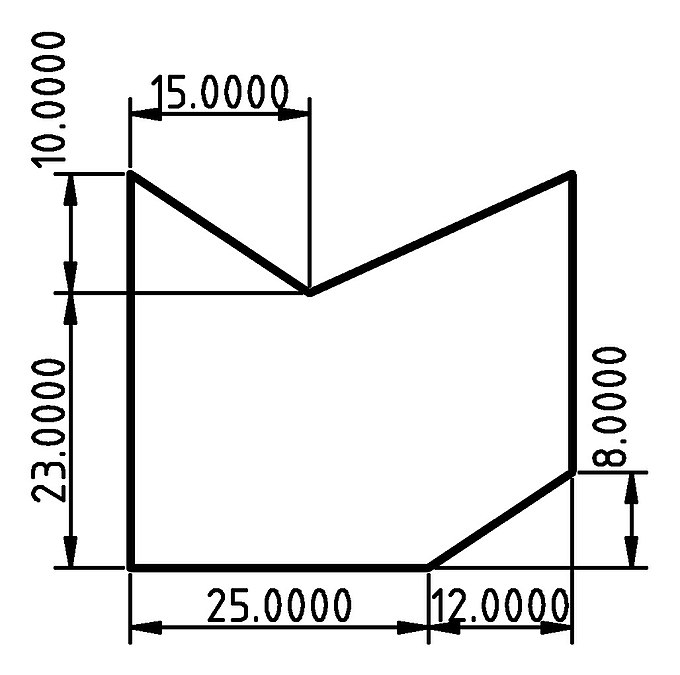
| Create the following 2D object using the polygon primitive. To do this you will need to define a list that contains the pairs of X and Y coordinates of the object’s points. Remember that the points should be defined in an appropriate order. You should first store the coordinates of each point on separate variables named p0, p1, p2, … and then define a list of all points and store it in a variable named points. This list will be passed on the polygon command. The definition of each point’s coordinates should be parametric in relation to the given dimensions which can be achieved by using appropriate mathematical expressions. To do this you will also need to define a variable for each given dimension. |
|
profile_2_polygon.scad
// Given dimensions h1 = 23; h2 = 10; h3 = 8; d1 = 25; d2 = 12; d3 = 15; // Points p0 = [0, 0]; p1 = [0, h1 + h2]; p2 = [d3, h1]; p3 = [d1 + d2, h1 + h2]; p4 = [d1 + d2, h3]; p5 = [d1, 0]; points = [p0, p1, p2, p3, p4, p5]; // Polygon polygon(points); |
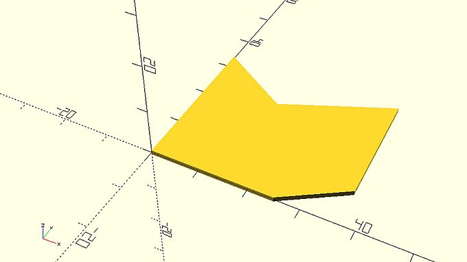
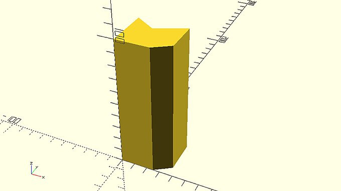
| Using the linear_extrude and rotate_extrude commands create a tube and a ring respectively that have the above profile. The tube should have a height of 100 units. The ring should have an inner diameter of 100 units. How many units do you need to translate the 2d profile along the positive direction of the X axis to achieve this? |
|
linearly_extruded_polygon.scad
…
linear_extrude(height=100)
    polygon(points);
…
|
|
rotationaly_extruded_polygon.scad
…
rotate_extrude(angle=360)
    translate([50,0,0])
    polygon(points);
…
|
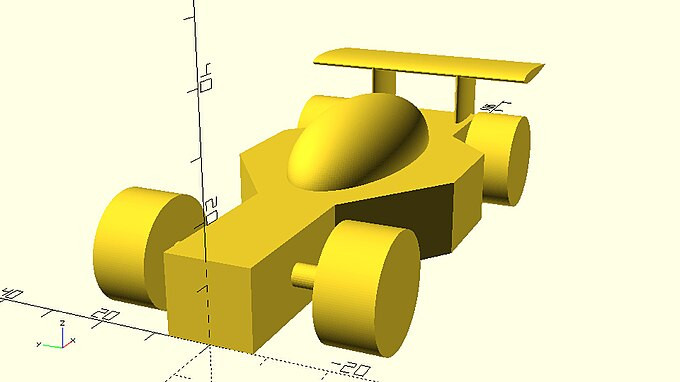
It’s time to use your new skills to create UwU racing car!
::现在是时候用你的新技能创造UuU赛车了!
| Create the above car body using the polygon command. To do so you will have to define each point of the design, add them all on a list and pass this list to the polygon command. The definition of each point’s coordinates should be parametric in relation to the given dimensions. Remember that in order to do this you will have to define a variable for each given dimension and calculate each point’s coordinates from these variables using appropriate mathematical expressions. You should extrude the created 2D profile to a height of 14 units. |
|
racing_car_body.scad
// model parameters
d1=30;
d2=20;
d3=20;
d4=10;
d5=20;

w1=15;
w2=45;
w3=25;

h=14;

// right side points
p0 = [0, w1/2];
p1 = [d1, w1/2];
p2 = [d1 + d2, w2/2];
p3 = [d1 + d2 + d3, w2/2];
p4 = [d1 + d2 + d3 + d4, w3/2];
p5 = [d1 + d2 + d3 + d4 + d5, w3/2];

// left side points
p6 = [d1 + d2 + d3 + d4 + d5, -w3/2];
p7 = [d1 + d2 + d3 + d4, -w3/2];
p8 = [d1 + d2 + d3, -w2/2];
p9 = [d1 + d2, -w2/2];
p10 = [d1, -w1/2];
p11 = [0, -w1/2];

// all points
points = [p0, p1, p2, p3, p4, p5, p6, p7, p8, p9, p10, p11];

// extruded body profile
linear_extrude(height=h)
    polygon(points);
|
| As mentioned previously, you can use additional variables to increase the readability of your script and to avoid repeating mathematical operations. Can you find a way to do so in the above script? |
|
racing_car_body_with_extra_variables.scad
// model parameters
d1=30;
d2=20;
d3=20;
d4=10;
d5=20;

w1=15;
w2=45;
w3=25;

h=14;

// distances to lengths
l1 = d1;
l2 = d1 + d2;
l3 = d1 + d2 + d3;
l4 = d1 + d2 + d3 + d4;
l5 = d1 + d2 + d3 + d4 + d5;

// right side points
p0 = [0, w1/2];
p1 = [l1, w1/2];
p2 = [l2, w2/2];
p3 = [l3, w2/2];
p4 = [l4, w3/2];
p5 = [l5, w3/2];

// left side points
p6 = [l5, -w3/2];
p7 = [l4, -w3/2];
p8 = [l3, -w2/2];
p9 = [l2, -w2/2];
p10 = [l1, -w1/2];
p11 = [0, -w1/2];

// all points
points = [p0, p1, p2, p3, p4, p5, p6, p7, p8, p9, p10, p11];

// extruded body profile
linear_extrude(height=h)
    polygon(points);
|
| Try completing the racing car design by adding the remaining objects to the above body. |

|
racing_car.scad
use <vehicle_parts.scad>

$fa = 1;
$fs = 0.4;

// model parameters
d1=30;
d2=20;
d3=20;
d4=10;
d5=20;

w1=15;
w2=45;
w3=25;

h=14;
track=40;

// distances to lengths
l1 = d1;
l2 = d1 + d2;
l3 = d1 + d2 + d3;
l4 = d1 + d2 + d3 + d4;
l5 = d1 + d2 + d3 + d4 + d5;

// right side points
p0 = [0, w1/2];
p1 = [l1, w1/2];
p2 = [l2, w2/2];
p3 = [l3, w2/2];
p4 = [l4, w3/2];
p5 = [l5, w3/2];

// left side points
p6 = [l5, -w3/2];
p7 = [l4, -w3/2];
p8 = [l3, -w2/2];
p9 = [l2, -w2/2];
p10 = [l1, -w1/2];
p11 = [0, -w1/2];

// all points
points = [p0, p1, p2, p3, p4, p5, p6, p7, p8, p9, p10, p11];

// extruded body profile
linear_extrude(height=h)
    polygon(points);

// canopy
translate([d1+d2+d3/2,0,h])
    resize([d2+d3+d4,w2/2,w2/2])
    sphere(d=w2/2);

// axles
l_front_axle = d1/2;
l_rear_axle = d1 + d2 + d3 + d4 + d5/2;
half_track = track/2;

translate([l_front_axle,0,h/2])
    axle(track=track);
translate([l_rear_axle,0,h/2])
    axle(track=track);

// wheels
translate([l_front_axle,half_track,h/2])
    simple_wheel(wheel_width=10);
translate([l_front_axle,-half_track,h/2])
    simple_wheel(wheel_width=10);

translate([l_rear_axle,half_track,h/2])
    simple_wheel(wheel_width=10);
translate([l_rear_axle,-half_track,h/2])
    simple_wheel(wheel_width=10);
|
Creating more complex object using the polygon primitive and math
::使用多边形原始和数学创建更复杂的对象
From the above examples it should be quite obvious that the polygon primitive opens up possibilities to create objects that would hardly be possible by just using the fundamental 2D or 3D primitives. In these examples you created custom 2D profiles by defining the coordinates of their points according to a given design. To unlock the true power of the polygon command though, and to create even more complex and impressive designs, you have to programmatically define the points of your profiles using math. This is because defining each point separately is not scalable to the hundreds of points that are required to design smooth non-square profiles. One example of this is the following heart. Can you manually define the required points to create it? There is no way.
::从上述例子中,很明显,多边形原始开启了创建仅仅使用基本的二维或三维原始几乎不可能实现的对象的可能性.在这些例子中,您通过根据给定的设计定义其点的坐标来创建自定义的二维配置文件.然而,为了解锁多边形命令的真正力量,并创建更复杂和令人印象深刻的设计,您必须使用数学程序来定义您的配置文件的点.这是因为单独定义每个点是无法扩展到设计光滑非正方形配置文件所需的数百个点.其中一个例子是以下的心脏.您可以手动定义创建它所需的点吗?没有办法.

Instead of manually defining each point, which would be practically impossible, this model was programmatically defined using the following parametric equations.
::没有手动定义每个点,这实际上是不可能的,这个模型是通过下列参数方程来编程定义的.
x = 16⋅sin(t)
3
y = 13⋅cos(t) − 5⋅cos(2⋅t) − 2⋅cos(3⋅t) − cos(4⋅t)
:: () () () () () () () () () () () () () () () () () () () () () () () () () () () ) () () () () () () ) () () ) () ) ()
When the range of the t variable covers values from 0 to 360 degrees, the above equations give the X and Y coordinates for the outline of the heart, starting from the top middle point and moving in a clockwise direction. Using the above equations, a list that contains each point’s coordinates can be generated in the following way.
::当t变量的范围涵盖0到360度的值时,上述方程给出心脏轮的X和Y坐标,从顶部的中间点开始,并以时针方向移动.使用上述方程,可以以以下方式生成包含每个点坐标的列表.
points = [ for (t=[0:step:359.999]) [16*pow(sin(t),3), 13*cos(t) - 5*cos(2*t) - 2*cos(3*t) - cos(4*t)]]; |
There are a few things you should notice about the syntax of list generation. First the name of the variable where the list will be stored is typed out. Then follows the equal sign (as in every variable assignment) and a pair of square brackets. Inside the pair of square brackets, the first thing that is typed out is the keyword
for
. After the keyword
for
follows a pair of parentheses inside of which the consecutive values that the corresponding variable is going to take are defined. This variable is similar to the for loop variable encountered in for loops. The number of elements that the generated list is going to have is equal to the number of values that this variable is going to take. For every value that this variable takes, one element of the list is defined. What each element of the list is going to be, is specified after the closing parenthesis. In this case each element of the generated list is itself a list that has two elements, one for each coordinate of the corresponding point. The
t
variable goes from 0 to 360 which is the required range to produce the whole outline of the heart. Since the polygon shouldn't include duplicate points, 359.999 is used instead of 360. By choosing a smaller or bigger value for the step variable, the amount of points that will be created can be controlled. Specifically, in order to create n points the step variable needs to be defined in the following way.
::列表生成的语法有一些你应该注意的事情.首先是列表将存储的变量的名称.然后是等号 (如每一个变量赋值) 和一对方括号.在两对方括号内,首先输入的是关键字for.在关键字for之后,接着是一对括号,其中相应变量将采取的连续值被定义.这个变量类似于for循环中遇到的for变量循环.生成的列表将具有的元素的数量等于这个变量将采取的值的数量.对于每个变量所取的较小值,列表中的一个元素被定义.列表中的每个元素将被指定后的括号.在这种情况下,生成的列表本身是一个列表,每个元素都有两个元素,每个元素对应的关键字为一个.由于选择
step = 360/n; |
Putting all these together, the heart can be created with the following script.
::通过将所有这些结合起来,
|
heart.scad
n = 500;
h = 10;
step = 360/n;
points = [ for (t=[0:step:359.999]) [16*pow(sin(t),3), 13*cos(t) - 5*cos(2*t) - 2*cos(3*t) - cos(4*t)]];
linear_extrude(height=h)
    polygon(points);
|
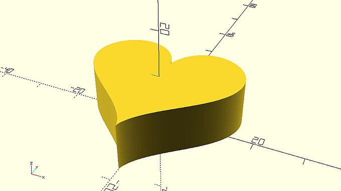
You can see that by using 500 points the resolution of the outline is very good.
::通过500点, 您可以看到大纲的分辨率非常好.
| Modify the above script so that the outline of the heart is consisted out of 20 points. |
|
heart_low_poly.scad
… n = 20; … |

Using more or less points is up to you. If you want to create an object that closely resembles the underlying mathematical equations, you should increase the number of points. Instead, if you opt for a low poly style you should decrease the number of points.
::选择多点或少点取决于你.如果你想创建一个与基础数学方程非常相似的对象,你应该增加点数.相反,如果你选择低多元风格,你应该减少点数.
Time for some quick list generation practice before you move on. Use the newly introduced syntax (variable = [ for (i=[start:step:end]) … ]; ) to generate the following lists:
|
Solution for exercise i, [1, 2, 3, 4, 5, 6]:
::练习i的解法 [1, 2, 3, 4, 5, 6]:
x = [ for (i=[1:6]) i]; |
Solution for exercise ii, [10, 8, 6, 4, 2, 0, -2]:
::练习 ii 的解法 [10, 8, 6, 4, 2, 0, -2]:
x = [ for (i=[10:-2:-2]) i]; |
Solution for exercise iii, [[3, 30], [4, 40], [5, 50], [6, 60]]:
::对于练习iii, [[3, 30], [4, 40], [5, 50], [6, 60]]的解决方案:
x = [ for (i=[3:6]) [i, i*10]]; |
Note that when no step is provided, a default of 1 is used.
::注意,如果没有提供任何步骤,则默认使用1.
OpenSCAD also allows you to define your own mathematical functions, which can be useful when a mathematical expression is particularly long, or when you would like to use it multiple times. These functions work similarly to modules, except that instead of defining a design they define a mathematical process. After a function has been defined, you can use it by invoking its name and providing the necessary input parameters. For example, you can define a function that accepts the parameter t, and returns the X and Y coordinates of the corresponding point of the heart's outline.
::OpenSCAD还允许您定义自己的数学函数,这在数学表达式特别长时或您想多次使用时可能很有用.这些函数与模块类似,只不过它们定义不仅设计,而是定义数学过程.在定义了一个函数后,您可以通过调用它的名称和提供必要的输入参数来使用它.例如,您可以定义一个接受参数t的函数,并返回心脏轮对应点的X和Y坐标.
function heart_coordinates(t) = [16*pow(sin(t),3), 13*cos(t) - 5*cos(2*t) - 2*cos(3*t) - cos(4*t)]; |
In this case the script that creates the heart would take the following form.
::在这种情况下, 创造心脏的脚本将采取以下形式.
n = 500;
h = 10;
step = 360/n;
function heart_coordinates(t) = [16*pow(sin(t),3), 13*cos(t) - 5*cos(2*t) - 2*cos(3*t) - cos(4*t)];
points = [ for (t=[0:step:359.999]) heart_coordinates(t)];
linear_extrude(height=h)
    polygon(points);
|
There are a few things you should notice about the definition of a function. First the word function is typed out. Then follows the name that you want to give to the function. In this case the function is named heart_coordinates. After the name of the function follows a pair of parentheses that contains the input parameters of the function. Like module parameters, the input parameters in a function can have default values. In this case, the only input parameter is the polar angle of the current step t and it’s not given a default value. After the closing parenthesis follows the equal sign and the command that defines the pair of X and Y coordinates of the heart’s outline.
::函数定义有几个要注意的方面.首先是键入函数字.接下来是你想要给函数的名称.在这种情况下,函数的名字叫做心_坐标.在函数名称之后,接下来是一对括号,包含函数的输入参数.像模块参数一样,函数中的输入参数可以具有默认值.在这种情况下,唯一的输入参数是当前步骤t的极角,它没有给定默认值.在闭括号之后,等号和命令接下来定义心轮的 X 和 Y 坐标对.
The generation of the list of points can also be turned in a function. This can be done in a similar fashion as follows.
::列表中的点也可以转换为函数.
function heart_points(n=50) = [ for (t=[0:360/n:359.999]) heart_coordinates(t)]; |
In this case the script that creates the heart would take the following form.
::在这种情况下, 创造心脏的脚本将采取以下形式.
n=20;
h = 10;
function heart_coordinates(t) = [16*pow(sin(t),3), 13*cos(t) - 5*cos(2*t) - 2*cos(3*t) - cos(4*t)];
function heart_points(n=50) = [ for (t=[0:360/n:359.999]) heart_coordinates(t)];
points = heart_points(n=n);
linear_extrude(height=h)
    polygon(points);
|
In short you should remember that any command that returns a single value or a list of values can be turned into a function. Like modules, functions should be used to organize your designs and make them reusable.
::总之,你应该记住任何返回单个值或值列表的命令都可以变成函数.像模块一样,函数应该用来组织你的设计并使它们可重复使用.
| Since you have already defined the function for generating the list of points that is required to create a heart, it would be a good idea to also define a module that creates a heart. Create a module named heart. The module should have two input parameter h and n corresponding to the height of the heart and the number of points used. The module should call the heart_points function to create the required list of points and then pass that list to a polygon command to create the 2D profile of the heart. This profile should be extruded to the specified height. |
|
heart.scad
…
module heart(h=10, n=50) {
    points = heart_points(n=n);
    linear_extrude(height=h)
        polygon(points);
}
…
|
| You can save the heart_coordinates and heart_points functions along with the heart module on a script named heart.scad and add it on your libraries. Every time you want to include a heart on a design that you are working on, you can use the use command to make the functions and modules of this script available to you. |
Another challenge
::另一个挑战
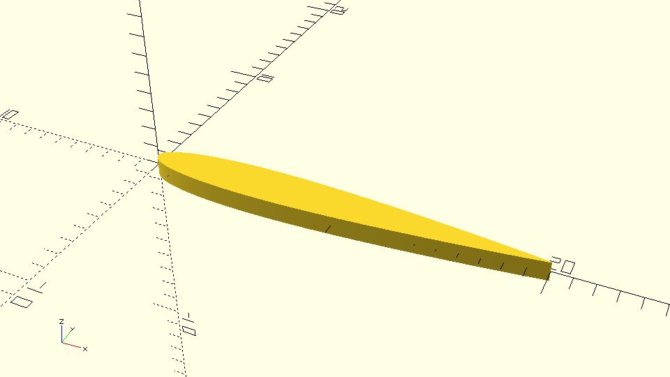
You are going to put your new skills into practice to create an aerodynamic spoiler for your racing car!
::您将将自己的新技能付诸实践, 为您的赛车制造空气动力学波器!
|
You are going to use a symmetrical 4-digit NACA 00xx airfoil for your spoiler. The half thickness of such an airfoil on a given point x is given by the following formula:
In the above formula, x is the position along the chord with 0 corresponding to the leading edge and 1 to the trailing edge, while t is the maximum thickness of the airfoil expressed as a percentage of the chord. Multiplying t by 100 gives the last two digits in the NACA 4-digit denomination.
|

|
naca_airfoil_module.scad
… function naca_half_thickness(x,t) = 5*t*(0.2969*sqrt(x) - 0.1260*x - 0.3516*pow(x,2) + 0.2843*pow(x,3) - 0.1015*pow(x,4)); … |
|
Create a function named naca_top_coordinates. This function should return a list of the X and Y coordinates for the top half of the airfoil. The first point should correspond to the leading edge while the last point should correspond to the trailing edge.
The function should have two input parameters: t and n. The parameter t should correspond to the airfoil’s maximum thickness, while the parameter n should correspond to the number of created points. The list of points should be generated using an appropriate list generation command. You will need to call the naca_half_thickness function.
|
|
naca_airfoil_module.scad
… function naca_top_coordinates(t,n) = [ for (x=[0:1/(n-1):1]) [x, naca_half_thickness(x,t)]]; … |
| Create a similar function named naca_bottom_coordinates that returns a list of points for the bottom half of the airfoil. This time the points should be given in reverse order. The first point should correspond to the trailing edge while the last point should correspond to the leading edge. This is done so that when the lists that are generated from the naca_top_coordinates and naca_bottom_coordinates functions are joined, all point of the airfoil are defined in a clockwise direction starting from the leading edge, thus making the resulting list suitable for use with the polygon command. |
|
naca_airfoil_module.scad
… function naca_bottom_coordinates(t,n) = [ for (x=[1:-1/(n-1):0]) [x, - naca_half_thickness(x,t)]]; … |
| Create a function named naca_coordinates that joins the two lists of points. You can use OpenSCAD's built in function “concat” to join lists together. Pass both lists as inputs to concat to join them together. |
|
naca_airfoil_module.scad
… function naca_coordinates(t,n) = concat(naca_top_coordinates(t,n), naca_bottom_coordinates(t,n)); … |
| Try using the naca_coordinates function to create a list that contains the points for an airfoil with a maximum thickness of 0.12 and with 300 points on each half. The list should be stored in a variable named points. The points variable should be passed to a polygon command to create the airfoils 2D profile. |
|
small_airfoil_polygon.scad
… points = naca_coordinates(t,n); polygon(points); … |
| The chord of the above airfoil is 1 unit. Can you use an appropriate scale command to enlarge the airfoil? The desired chord should be defined on a variable named chord and the scale command should be defined in relation to this variable. Create an airfoil that has a chord of 20 units. |
|
scaled_airfoil_polygon.scad
…
chord = 20;
points = naca_coordinates(t=0.12,n=300);
scale([chord,chord,1])
    polygon(points);
…
|
| Turn the above script into a module named naca_airfoil. The module should have three input parameter, chord, t and n. There shouldn’t be default values for any of the input parameters. |
|
naca_airfoil_module.scad
module naca_airfoil(chord,t,n) {
    points = naca_coordinates(t,n);
    scale([chord,chord,1])
        polygon(points);
}
|
| All you have to do now to create a wing out of the airfoil is to apply a linear_extrude command on the 2D airfoil profile. Create a module named naca_wing that does that. The naca_wing module should have two additional input parameters compared to the naca_airfoil module, span and center. The span parameter should correspond to the height of the extrusion while the center parameter should dictate whether the extrusion is executed along only the positive direction of the Z axis or along both directions. The span parameter shouldn’t have a default value while the default value of the center parameter should be false. Can you use the naca_wing module to create the following wing? The following wing has a span of 50 units, while the airfoil of the wing has a chord of 20 units, a maximum thickness of 0.12 and 500 points on each half. You will have to additionally use a rotation transformation to place the wing as in the following image. |
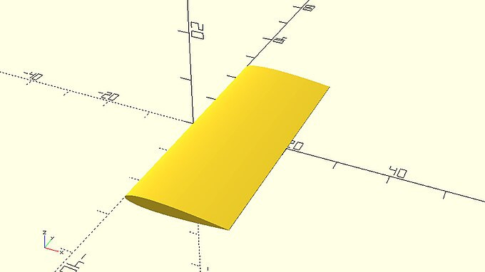
|
spoiler_wing.scad
…
module naca_wing(span,chord,t,n,center=false) {
    linear_extrude(height=span,center=center) {
        naca_airfoil(chord,t,n);
    }
}
…
rotate([90,0,0])
    naca_wing(span=50,chord=20,t=0.12,n=500,center=true);
…
|
| Use the naca_wing module to add two smaller vertical wings on the previous example in order to create the spoiler of the car. The smaller wings should have a span of 15 units as well as a chord of 15 units. |
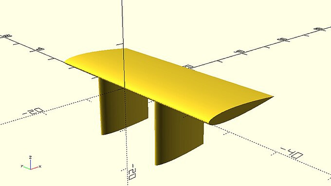
|
spoiler.scad
…
rotate([90,0,0])
    naca_wing(span=50,chord=20,t=0.12,n=500,center=true);
translate([0,10,-15])
    naca_wing(span=15,chord=15,t=0.12,n=500);
translate([0,-10,-15])
    naca_wing(span=15,chord=15,t=0.12,n=500);
…
|
| Add the above spoiler on the racing car design to complete it. |

|
racing_car_with_spoiler.scad
use <vehicle_parts.scad>

$fa = 1;
$fs = 0.4;

// model parameters
d1=30;
d2=20;
d3=20;
d4=10;
d5=20;

w1=15;
w2=45;
w3=25;

h=14;
track=40;

// distances to lengths
l1 = d1;
l2 = d1 + d2;
l3 = d1 + d2 + d3;
l4 = d1 + d2 + d3 + d4;
l5 = d1 + d2 + d3 + d4 + d5;

// right side points
p0 = [0, w1/2];
p1 = [l1, w1/2];
p2 = [l2, w2/2];
p3 = [l3, w2/2];
p4 = [l4, w3/2];
p5 = [l5, w3/2];

// left side points
p6 = [l5, -w3/2];
p7 = [l4, -w3/2];
p8 = [l3, -w2/2];
p9 = [l2, -w2/2];
p10 = [l1, -w1/2];
p11 = [0, -w1/2];

// all points
points = [p0, p1, p2, p3, p4, p5, p6, p7, p8, p9, p10, p11];

// extruded body profile
linear_extrude(height=h)
    polygon(points);

// canopy
translate([d1+d2+d3/2,0,h])
    resize([d2+d3+d4,w2/2,w2/2])
    sphere(d=w2/2);

// axles
l_front_axle = d1/2;
l_rear_axle = d1 + d2 + d3 + d4 + d5/2;
half_track = track/2;

translate([l_front_axle,0,h/2])
    axle(track=track);
translate([l_rear_axle,0,h/2])
    axle(track=track);

// wheels
translate([l_front_axle,half_track,h/2])
    simple_wheel(wheel_width=10);
translate([l_front_axle,-half_track,h/2])
    simple_wheel(wheel_width=10);

translate([l_rear_axle,half_track,h/2])
    simple_wheel(wheel_width=10);
translate([l_rear_axle,-half_track,h/2])
    simple_wheel(wheel_width=10);

// spoiler
use <naca.scad>

module car_spoiler() {
    rotate([90,0,0])
        naca_wing(span=50,chord=20,t=0.12,n=500,center=true);
    translate([0,10,-15])
        naca_wing(span=15,chord=15,t=0.12,n=500);
    translate([0,-10,-15])
        naca_wing(span=15,chord=15,t=0.12,n=500);
}

translate([l4+d5/2,0,25])
    car_spoiler();
|