Blender 3D:第四单元:与高级教程起飞
Bump Maps are textures that store the relative height of pixels from the viewpoint of the camera. The pixels seem to be moved in the direction of the facenormals, either in direction to or away from the camera. You may either use greyscale pictures or the intensity values of an RGB-Texture (including images).
::凸图图是从相机的视角存储像素的相对高度的纹理.像素似乎在面向正常的方向移动,无论是向相机的方向还是远离相机.您可以使用灰度图像或RGB-Texture (包括图像) 的强度值.
|
|
|
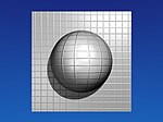
Bump Maps are easy to apply. They work well on flat surfaces, only to some extent on curved surfaces. On curved surfaces it is more easily noticeable that you don't create real 3D structures. The visible effect depends on factors like lighting, specularity of your material, camera angle, distance and so forth.
::凸点图很容易应用.它们在平面上很好,在曲面上只有一定程度.在曲面上,你更容易注意到你没有创建真正的3D结构.可见效应取决于诸如照明,材料的光谱性,摄像头角度,距离等因素.
-
Add a new texture to your object.
::给你的物体添加新的纹理. -
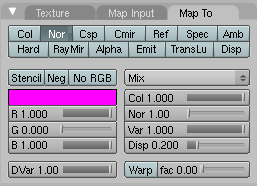
Activate the
Nor
button in the
Map To
panel.
::在"地图到"面板中激活"Nor"按. -
Set the depth of the bumping with the
Nor
slider.
::使用北滑块设置撞击深度. -
Use the texture type
Image
and load your bump map.
::使用图像类型加载你的凸图.
Bump maps should contain hard transitions between black and white. A gray wedge (e.g. a linear blend texture) would be hardly visible in the rendering.
::凸图应包含黑白之间的硬过渡.在染中几乎看不到灰色 (例如线性混合纹理).
Creating Bump Maps
::创建突破地图
You can easily create Bump Maps with Blender yourself, this is especially useful if you have modeled some small details on a surface and you realize at the end that your scene will get too complex. You could also use the Bump Maps in a 2D application like Gimp or other, similar programs.
::您可以使用Blender轻松地创建Bump Maps,如果您在表面上模拟了一些小细节,并且在最后意识到您的场景将变得过于复杂,这尤其有用.您也可以在Gimp或其他类似的程序中使用Bump Maps.
I will create an animated bump map in highest possible quality, it is not always necessary to make such an effort. The goal is to create a wave effect and make an image sequence of it, to be used as a bump map. The original object has 600.000 vertices, the object the map is applied to has 8 vertices.
::我将创建一个动画的撞击地图,在最高的质量,它并不总是需要这样的努力. 目标是创建一个波效应,并使一个图像序列,作为一个撞击地图. 原始对象有600,000顶点,对象地图被应用有8个顶点.
Setting up the scene
::准备情景
-
Open the default scene and remove the cube.
::打开默认场景并移除立方体. -
Insert a plane and change to edit mode.
::插入一个平面并切换到编辑模式. -
Crease its edges with +1 (
Shift-E
).
::通过+1 (Shift-E) 曲它的边缘. -
Subdivide multi
with 11 cuts.
::通过11个切片将多部分分成. -
Change to object mode.
::切换到对象模式. -
Add a
SubSurf
modifier with a render level of 6.
::添加一个具有6染级别的SubSurf修改器. -
Add a
Wave
modifier.
-
Time Sta:
-10
::时间: -10 -
Height:
0.2
::高度:0.2 -
Width:
1.5
::宽度:1.5 -
Narrow:
1.5
::狭窄:1.5 个
::添加波变量器. 时间站:10 高度:0.2宽度:1.5窄度:1.5 -
Time Sta:
-10
-
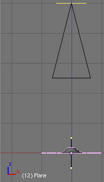
Set the camera dead upon the plane.
-
X/Y/Z:
0/0/5. You can use the
Transform Properties Panel
to bring the camera to a certain position, the Z-Position is important is this case.
::您可以使用转换属性面板将摄像机带到某个位置,Z-位置是重要的.
::设置相机死在飞机上. X/Y/Z: 0/0/5. 你可以使用转换属性面板将相机带到一个特定的位置,Z-位置是重要的是在这种情况下. -
X/Y/Z:
0/0/5. You can use the
Transform Properties Panel
to bring the camera to a certain position, the Z-Position is important is this case.
-
Set the camera lens to 80.00 (
Editing Buttons->Camera Panel
).
::设置摄像机镜头为 80.00 (编辑按->摄像机面板).
The plane should now fit exactly into the camera view.
::飞机现在应该完全符合摄像头的视图.
-
Save your file.
::保存你的文件.
We're going to use the Z-Buffer information to create the bump texture. The Z-Buffer contains the distance from the camera, this is exactly what a bump map is. To render the Z-Buffer information as an image, we're going to use
Composite
nodes. To get the highest possible quality, we will use
Open EXR
as file format, this allows us to store the Z-Buffer information with a numerical accuracy of 32-Bit floating point, instead of a meager 8-Bit value.
::我们将使用Z-Buffer信息来创建凸起纹理.Z-Buffer包含了相机的距离,这正是凸起图的特征.为了将Z-Buffer信息染成图像,我们将使用复合节点.为了获得最高的质量,我们将使用Open EXR作为文件格式,这使我们能够存储Z-Buffer信息,其数值精度为32位浮点,而不是微不足道的8位值.
Render settings
::渲染设置
-
Change to the
Anim
tab buttons (f10).
::转到动态标签按 (f10). -
Set
End
to 40.
::设置结束到40 -
Activate
Do Composite
.
::激活"复合"功能 -
Select
Open EXR
in the
Format
panel, set
SizeX/Y
to both 600 (square image for the square plane).
::在格式面板中选择打开EXR,将SizeX/Y设置为600 (方形图像为方形平面). -
Set the
Output
directory to
//BumpAnim/
. This creates a subdirectory to the file where the image sequence will be stored. Don't omit the slashes.
::将输出目录设置为 //BumpAnim/. 这将创建一个副目录到文件中, 图像序列将存储. 不要省略斜.
Node editor
::节点编辑器

Now the setup for the composite nodes.
::现在是复合节点的设置.
-
Open a
Node Editor
window.
::打开一个节点编辑器窗口. -
Select
Composite Nodes
.
::选择复合节点. -
Activate
Use Nodes
.
::激活使用节点.
A
Render Layer
and a
Composite
node will be inserted automatically.
::现在将自动插入一个染层和一个复合节点.
-
Add->Vector->Map Value
.
::添加->向量->地图值. -
Connect the
Z
-Output of the
Render Layer
to the
Value
input, and the
Value
output to the
Image
input of the
Composite
node.
::将染层的Z输出连接到Value输入,并将Value输出连接到复合节点的Image输入.
If you render now the image is plain white, we have to talk a bit about the
Map Value
node. The
Offs
value is the distance from the camera where the Z-Buffer should start (in negative BU). It is not to important to get the best range, because we use OpenEXR, but if you would like to use PNG instead, you have to select this value carefully.
::如果现在的图像是纯白色的,我们必须谈谈Map Value节点.Offs值是Z-Buffer应该从相机开始的距离 (负BU). 获得最佳范围并不重要,因为我们使用OpenEXR,但如果您想使用PNG,您必须仔细选择这个值.
-
Set
Offs
to
-4.8
. This is the smallest distance from the camera needed. You can measure this value if you use the
Camera Clipping
, or if you render and move your mouse with pressed
LMB
above the render window.
::设置Offs为-4.8. 这是从相机所需的最小距离. 如果使用相机剪辑,或者如果染并将鼠标按住LMB移动在染窗口上方,则可以测量此值. -
Set
Size
to 4. The size value is a bit complicated. This is not directly the value range, instead
, and
.
-
If you want to include the Z-Values from -4.8 up to -5.05 the range is 0.25, so
Size
is 4.
::如果我们想包括从 -4.8 到 -5.05 的 Z 值, 范围是 0.25, 所以大小是 4. -
If you want to include the Z-Values from -4.5 to -3.5 the range would be -1, so
Size
would be also -1.
::如果我们想把Z值从-4.5到-3.5包括在内, 范围是-1 所以大小也会是-1. -
If you want to include the Z-Values from -4.5 to -5.5, the range would be 1, so
Size
would be 1.
::如果我们想包括从 -4.5到 -5.5的 Z 值, 范围是 1, 所以大小是 1.
::设置大小为4.大小值有点复杂.这不是直接的值范围,而是r a n g e = 1 s i z e,和s i z e = 1 r a n g e.如果你想包括从 -4.8到 -5.05的Z值,范围是0.25,所以大小是4.如果你想包括从 -4.5到 -3.5的Z值,范围将是 -1,所以大小也将是 -1.如果你想包括从 -4.5到 -5.5的Z值,范围将是1,所以大小将是1. -
If you want to include the Z-Values from -4.8 up to -5.05 the range is 0.25, so
Size
is 4.
 , and
, and
 .
.
-
Render the animation.
::提供动画.
Applying the animated bump map
::应用动画撞击地图
-
Open a new file.
::打开一个新的文件. -
Select the default cube and change to the
Texture
buttons.
::选择默认的立方体,然后切换到纹理按. -
Use the texture type
Image
.
::使用纹理类型的图像. -
Load the first OpenEXR-Image from the directory where you have stored the sequence.
::从您存储序列的目录上加载第一个OpenEXR-Image. -
Activate
Sequence
in the
Image
panel, set
Frames
to 40.
::在图像面板激活序列,设置到40 -
Change to the
Material
buttons.
::切换到"材料"按. -
Activate
Nor
for the texture and set the
Nor
slider to 25 in the
Map To
panel.
::在"地图到"面板中, 激活"nor"以获得纹理, 并将"nor"滑块设置为25. -
Set the mapping to
Cube
in the
Map Input
panel.
::在地图输入面板中将映射设置为立方体.
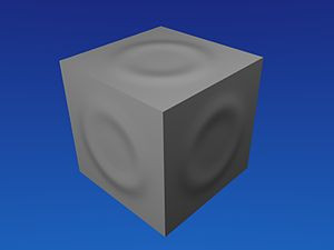
This is it. Pretty much the same look as with the real deformation, but using much less resources.
::这就是它. 几乎与真正的变形相同,