OpenSCAD教程
A few words about OpenSCAD
::关于OpenSCAD的一些话
OpenSCAD is for crafting 3D models through the art of Constructive Solid Geometry. It unlocks a world of creativity, where elementary operations are like our building blocks.
::通过构造型实体几何学, 打开一个创造性的世界, 基本操作就像我们的构建块.
Let's shape up some fun.
::我们来搞个好玩吧.
Getting started with the Tutorial
::开始使用教程
This tutorial will be your trusted guide. We'll be exploring examples and unveil the secrets of OpenSCAD. By the end of this tutorial, you will have the tools to forge your own unique 3D models, line by line.
::通过这个教程,我们将探索 OpenSCAD 的例子,揭开 OpenSCAD 的秘密. 在这个教程结束时,你将拥有工具来逐行造你自己的独特的 3D 模型.
With each step, you'll gain confidence and expertise, honing your skills as an image creator. You will breathe code into your designs, crafting intricate structures and bringing your design ideas to fruition.
::通过每一步的学习,你都会获得自信和专业知识, 磨练你的图像创作技巧. 你将把代码融入你的设计中, 制作复杂的结构,
Throughout this tutorial, we'll be your companion, offering guidance to unlock the full potential of OpenSCAD.
::通过这个教程, 我们将成为你的伴侣, 提供指导, 释放OpenSCAD的全部潜力.
You'll explore, learn, and create.
::您将探索,学习和创造.
User Interface
::使用者界面
After starting OpenSCAD the window should look similar to the image below.
::启动OpenSCAD后,窗口应该与下面的图像相似.
The Window is divided in three columns.
::窗户分为三个列.
-
In the left column, is seen the builtin text editor, where the true magic unfolds. As you enter keyboard commands you can view the transformation of code into art.
::您可以看到内置的文本编辑器, 展现真正的魔力. 当您输入键盘命令时, -
In the middle column, the displayed 3D View is where your design creations come to life. At the bottom lies the operations sequence console, always ready to lend a helping hand. It unravels the mysteries of mistakes and guides you towards mastery. It is your trusted guidance companion.
::在中列,显示的3D视图是您的设计创作生动的地方.在底部是操作序列控制台,总是准备帮忙.它揭开了错误的奥秘,并引导您向掌握.它是您可信的指导伙伴. -
And note the right column, the GUI Customizer. It offers the user a gift of ease toolbar, a graphical interface to tweak and twist your model's parameters.
::并且注意右侧的专, GUI Customizer. 它为用户提供了一个简单的工具,一个图形界面来调整和扭曲模型的参数.
Creating your first object
::创建您的第一个对象
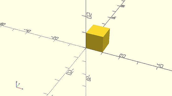
Your first object is going to be a perfect cube with side length of 10. In order to create it you need to type the following code in the text editor and hit the preview (first) icon on the action bar below the reference axes.
::您的第一个对象将是一个边长为10的完美立方体. 为了创建它,您需要在文本编辑器中输入以下代码,然后在参考轴下方的动作上点击预览 (第一个) 图标.
|
a_small_cube.scad
cube(10); |
There are a few fundamental concepts that you should learn from the start regarding the OpenSCAD scripting language, especially if you don’t have a programming background. The word 'cube' is part of OpenSCAD scripting language and is used to command OpenSCAD to create a cube. The 'cube' command is followed by a pair of parentheses, inside of which the parameter size is defined to be 10. Any definition of parameters that a command may require is always done inside a pair of matching parentheses that follow the command word. The semicolon after the last parenthesis indicates the end of that statement and helps OpenSCAD to parse the script that you have typed in the text editor. Because a semicolon is used to indicate the end of each statement you have the freedom to format your code in any way you like by inserting whitespace.
::关于OpenSCAD脚本语言,你应该从一开始就学习一些基本概念,特别是如果你没有编程背景. '立方体'这个词是OpenSCAD脚本语言的一部分,它用于命令OpenSCAD创建一个立方体. '立方体'命令后面有一对括号,其中参数大小定义为10. 命令可能需要的任何参数定义总是在命令单词后面的一对匹配括号内完成的.最后一个括号后的半点母符号表示该语句的末尾,并帮助OpenSCAD解析你在文本编辑器中输入的脚本. 因为半点母符号用于表示每个语句末尾,你有自由以任何方式格式化你的代码,只要插入白空间.
| Try adding some whitespace between the word 'cube' and the first parenthesis and then hit (select) the "preview" option. Is your cube created? Do you get any error message? Try adding some additional whitespace in different places and hit "preview" again to see what you can get away with before getting an error message in the console. What happens if you add whitespace between the syllables 'cu' and 'be' of the word 'cube' and hit "preview"? What happens if you delete the semicolon? |
You just read "hit preview" three times in the last paragraph. When you hit "preview" OpenSCAD parses your script and creates the appropriate model. Every time you make a change to your script (ex. adding whitespace) or later when adding additional statements, you need to hit "preview" to see the effect of these changes.
::你刚刚在最后一段读了三次"打预览".当你打"预览"时,OpenSCAD会解析你的脚本并创建适当的模型.每次你对脚本进行更改 (例如添加空白) 或稍后添加额外的语句时,你需要打"预览"以查看这些更改的影响.
| Try changing the size of the cube to 20 and see what happens. Did you remember to hit preview in order to see your changes take place? |
Creating a slightly different cube
::创建一个稍微不同的立方体
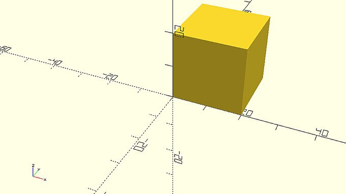
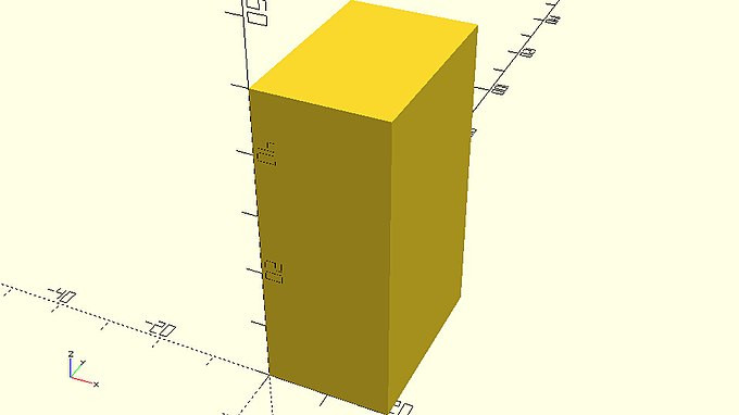
A cube doesn’t have to be perfect (equal distance). A cube can (be cubical) have different side lengths. Use the following statement to create a cube (cubical) with side lengths of 25, 35 and 55.
::一个立方体不一定是完美的 (距离相同).一个立方体可以 (是立方体) 有不同的边长.使用以下语句创建一个立方体 (立方体) 的边长为 25,35 和 55.
|
a_different_cube.scad
cube([25,35,55]); |
The first thing that you should notice is that this cube is quite large compared to the previous one. In fact, it is large enough that it doesn’t fit in the viewport. In order to fix this, you can move your mouse over the viewport and scroll out until you can see the whole cube. You can always zoom in and out by moving your mouse over the viewport and using the scroll wheel. Alternatively, you can use the zoom in (fourth) and out (fifth) icons on the action bar below the viewport. You can let OpenSCAD automatically choose a convenient zoom level by using the view all (third) icon in the same action bar.
::首先你应该注意到的是,这个立方体相比之前的立方体相当大.事实上,它足够大,它不适合在视窗中.为了解决这个问题,你可以把鼠标移动在视窗上,然后滚动到外面,直到你能看到整个立方体.你可以随时通过移动鼠标在视窗上,并使用滚动轮来缩放和缩小. 另外,你可以使用视窗下方的动作上的缩放 (第四) 和缩小 (第五) 图标.你可以让OpenSCAD在同一个动作中使用视图所有 (第三) 图标来自动选择方便的缩放级别.
| Try moving your mouse over the viewport and using the scroll wheel to zoom in and out. Try zooming in and out using the corresponding icons. Let OpenSCAD choose a zoom level for you. |
Apart from zooming in and out you can also move and rotate the view of your model. To do so you need to move your mouse over the viewport and drag while holding right click to move or drag while holding left click to rotate. You can reset the view by using the reset view (sixth) icon on the action bar below the viewport.
::除了放大和缩小外,您还可以移动和旋转模型的视图.为了做到这一点,您需要将鼠标移动在视图窗口上,并拖动,同时按右键移动或拖动,同时按左键旋转.您可以通过视图窗口下方的动作上的重置视图 (第六个) 图标重置视图.
| Try dragging your mouse over the viewport while holding right or left click to move or rotate the view of your model. See how long you can mess around before you need to reset the view. |
The second thing that you should notice is that in order to create a cube with different side lengths you need to define a pair of brackets with three values inside the parentheses. The pair of brackets is used to denote a vector of values. The values of the vector need to be comma-separated and correspond to the cube side lengths along X, Y and Z axis. When the cube command is used with a vector of three values as its input, OpenSCAD creates a cube with different side lengths that correspond to the values of the vector. Remember that you previously used the cube command to create a perfect cube by defining the value of the parameter size. Most OpenSCAD commands can be used with different parameters, even with more, less or no parameters to achieve different results.
::第二个你应该注意的是,为了创建一个边长不同的立方体,你需要定义一个带有三个值的括号.括号对用于表示一个值向量.向量的值需要用逗号分隔,并且与沿 X,Y 和 Z 轴的立方体边长相对应.当立方体命令用一个带有三个值的向量作为输入时,OpenSCAD创建一个与向量的值相对应的不同边长的立方体.请记住,你以前使用了立方体命令来通过定义尺寸参数的值来创建一个完美的立方体.大多数OpenSCAD命令可以使用不同的参数,甚至有更多,更少或没有参数来实现不同的结果.
| Try using the cube command with no parameters. What happens? Use the cube command to create a cube with side lengths of 50, 5 and 10. Use the cube command to create a perfect cube with side length of 17.25. |
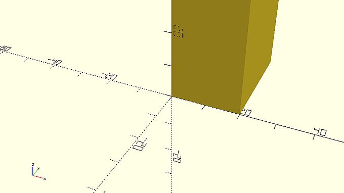
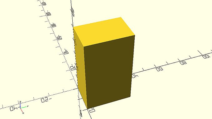
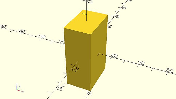
You should notice that every cube is created on the first octant. You can define an additional parameter named center and set it equal to true in order to make the cube centered on the origin. The complete statement is the following.
::你应该注意到每一个立方体都是在第一个八位数上创建的.你可以定义一个额外的参数,叫做 center,并将它设置为 true,以便使立方体以原点为中心.完整的语句如下.
|
a_centered_cube_with_different_side_lengths.scad
cube([20,30,50],center=true); |
Notice that when more than one parameter is defined inside the parentheses, they need to be separated with a comma.
::需要用逗号分开. 参数的定义是:
| Try creating a perfect cube or a cube with different side lengths. Use an appropriate additional input parameter to make this cube centered on the origin. If you like add some whitespace before and after the comma that separates the two parameters. |
Adding more objects and translating objects
::添加更多对象和翻译对象
The constructive solid modelling approach uses a number of fundamental objects along with a number of ways to transform and combine these objects to create more complex models. The cube that you have been using in the previous examples is one such fundamental object. The fundamental objects are also called primitives and are directly available in OpenSCAD scripting language. A car for example is not an OpenSCAD primitive, as there is no corresponding keyword in the scripting language. This makes absolute sense because OpenSCAD is a set of modelling tools rather than a library of predefined models. Using the available tools, you can combine the available primitives to create your own car. To do this you need to know how to add more than one object to your model.
::构造型固体建模方法使用了一些基本对象以及一些方法来转换和组合这些对象以创建更复杂的模型.你在以前的例子中使用的立方体是这样一个基本对象.基本对象也被称为原始,并且直接可在OpenSCAD脚本语言中使用.例如,汽车不是OpenSCAD原始,因为脚本语言中没有相应的关键字.这绝对是有意义的,因为OpenSCAD是一个建模工具集,而不是预定义模型库.使用可用的工具,你可以将可用的原始组合起来创建自己的汽车.为了做到这一点,你需要知道如何向模型添加多个对象.
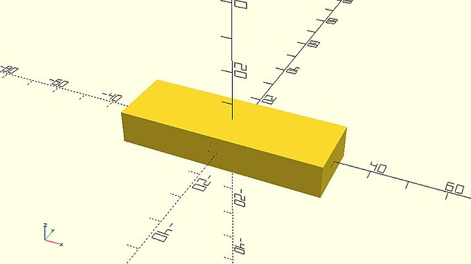
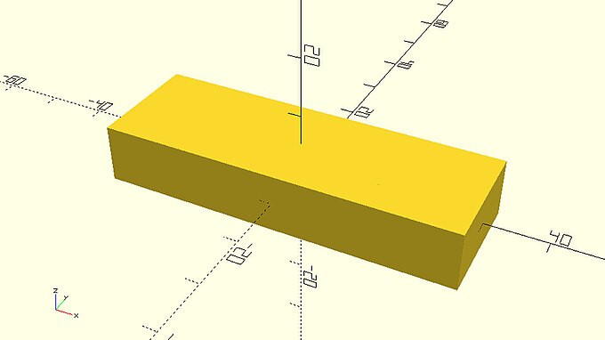
First create a cube with side lengths of 60, 20 and 10 that is centered on the origin.
::首先创建一个边长为60,20和10的立方体,
cube([60,20,10],center=true); |
In order to add a second cube to your model type an identical statement in the next line of the text editor, but change the side lengths to 30, 20 and 10.
::为了在你的模型中添加第二个立方体, 在文本编辑器的下一行输入一个相同的语句, 但改变侧面长度为30,20和10.
|
a_smaller_cube_covered_by_a_bigger_cube.scad
cube([60,20,10],center=true); cube([30,20,10],center=true); |
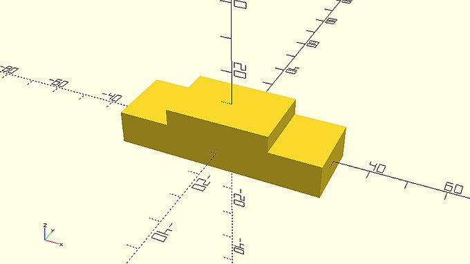
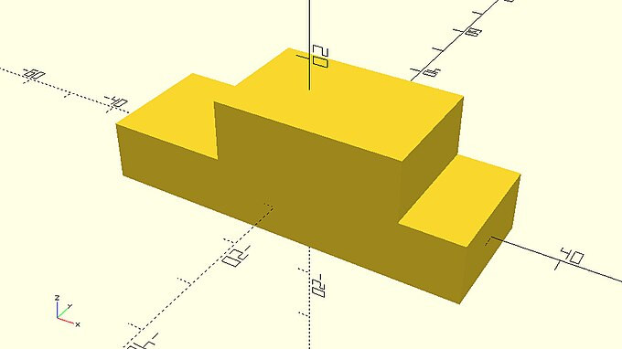
You should not be able to see any change in your model because the second cube is not larger than the first cube in any direction and is currently completely covered by the first cube. By modifying the second statement in the following way, you can translate the second cube to locate it partially above the top of the first cube.
::你不应该能够看到模型的任何变化,因为第二个立方体在任何方向都不大于第一个立方体,并且目前完全被第一个立方体覆盖.通过以下方式修改第二个语句,你可以翻译第二个立方体,以使其部分位于第一个立方体的顶部.
|
two_cubes.scad
cube([60,20,10],center=true);
translate([0,0,5])
    cube([30,20,10],center=true);
|
You achieved this by using the "translate" command which is one of the available transformations. The translate command as well as the rest of the transformations don’t create any object on their own. They are rather applied on existing objects to modify them in a certain way. The translate command can be used to move an object to any point in space. The input parameter for the translate command is a vector of three values. Each value indicates the amount of units that the object will be moved along the X, Y and Z axis. You should notice that there is no semicolon after the translate command. What follows the translate command is the definition of the object that you want to translate. The semicolon is added at the end to indicate the completion of the statement.
::你通过使用"translate"命令实现了这一目标,这是可用的转换之一. 转换命令以及其余的转换本身不会创建任何对象.它们而是应用于现有对象以某种方式修改它们. 转换命令可以用来将对象移动到空间中的任何点. 转换命令的输入参数是三个值的向量. 每个值表示对象将沿 X,Y 和 Z 轴移动的单位数量. 你应该注意到,转换命令后没有半点角. 转换命令之后是你想要转换的对象的定义. 半点角在最后添加,以表示语句的完成.
| Try changing the input parameter of the translate command so that the cube is translated 5 units along the X axis and 10 units along the Z axis. Try adding some whitespace if you would like to format this statement in a different way. Try adding a semicolon after the translate command. |
|
two_cubes_barely_touching.scad
cube([60,20,10],center=true);
translate([0,0,10])
    cube([30,20,10],center=true);
|
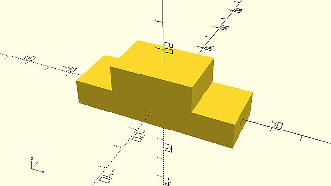
On the example above, the second cube sits exactly on top of the first cube. This is something that should be avoided as it’s not clear to OpenSCAD whether the two cubes form one object together. This issue can be easily solved by always maintaining a small overlap of about 0.001 - 0.002 between the corresponding objects. One way to do so is by decreasing the amount of translation along the Z axis from 10 unit to 9.999 units.
::在上面的例子中,第二个立方体正好位于第一个立方体的顶部.这是应该避免的,因为OpenSCAD不清楚两个立方体是否形成一个对象.这个问题可以很容易地通过始终保持对应对象之间的0.001 - 0.002的小重叠来解决.这样做的方法之一是将Z轴上的翻译量从10单位降低到9.999单位.
|
two_cubes_with_small_overlap.scad
cube([60,20,10],center=true);
translate([0,0,9.999])
    cube([30,20,10],center=true);
|
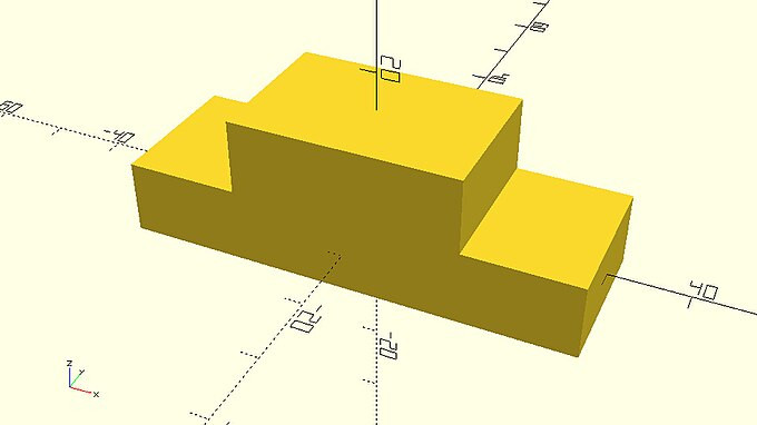
Another way to do so more explicitly is by subtracting 0.001 units from the corresponding value on the script.
::另一个更明确的方法是从脚本上的相应值减去0.001个单位.
|
two_cubes_with_explicit_small_overlap.scad
cube([60,20,10],center=true);
translate([0,0,10 - 0.001])
    cube([30,20,10],center=true);
|

There is a third way. For not losing 0.001 from the top we could add a third cube with dimensions like the smaller cube, and height of 0.002 ([30, 20, 0.002]). The third cube will close the gap.
::还有一个第三种方法.为了不从顶部丢失0.001我们可以添加第三个立方体,其尺寸与较小的立方体一样,高度为0.002 ([30,20,0.002]).第三个立方体将缩小差距.
|
third_cube_close_small_gap.scad
cube([60,20,10],center=true);
translate([0,0,10])
    cube([30,20,10],center=true);
translate([0,0,5 - 0.001])
    cube([30,20,0.002],center=true);
|
This is something you are going to encounter throughout the tutorial. When two objects are exactly touching each other, you should always guarantee a small overlap by subtracting or adding a tolerance of 0.001 units.
::两种物体正确地碰到对方时, 您应该通过减去或增加 0.001 个单位的宽容度来保证一个小的重叠.
The cylinder primitive and rotating objects
::圆柱原始和旋转的物体
The model that you just created looks like the body of a car that has bad aerodynamics. That’s ok. You will be making the car look a lot more interesting and aerodynamic in the following chapters. For now, you are going to use the cylinder primitive and the rotate transformation to add wheels and axles to your car. You can create a wheel by adding a third statement that consists of the cylinder command. You will need to define two input parameters, h and r. The first one will be the height of the cylinder while the second one will be its radius.
::你刚刚创建的模型看起来像一辆有着不良空气动力学的汽车的车身.没关系.你将在下面的章节中让汽车看起来更有趣和空气动力.现在,你将使用原始和旋转转换来添加车轮和轴.你可以通过添加第三个命令来创建一个轮.它包括命令.你需要定义两个输入参数,h和r.第一个是的高度,而第二个是它的半径.
|
a_cylinder_covered_by_cubes.scad
cube([60,20,10],center=true);
translate([5,0,10 - 0.001])
    cube([30,20,10],center=true);
cylinder(h=3,r=8);
|
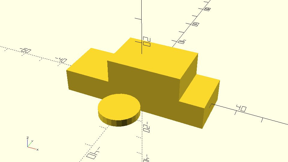
You should notice that the cylinder is hidden by the rest of the objects. You can use the translate command to make the cylinder visible by translating it 20 units along the negative direction of the Y axis.
::您可以使用转换命令使圆柱体可见, 通过将其转换为 20 个单位沿着负方向的 Y 轴.
|
two_cubes_and_a_cylinder.scad
cube([60,20,10],center=true);
translate([5,0,10 - 0.001])
    cube([30,20,10],center=true);
translate([0,-20,0])
    cylinder(h=3,r=8);
|
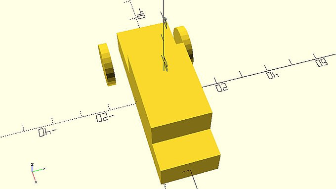
The wheel is now visible, but your car won’t go anywhere if its not properly placed. You can use the rotate command to make the wheel stand straight. To do so you need to rotate it 90 degrees around the X axis.
::现在轮子是可见的,但是如果不正确放置,你的车就不会去任何地方.你可以使用旋转命令使轮子直立.要做到这一点,你需要在X轴周围旋转90度.
|
two_cubes_and_a_rotated_cylinder.scad
cube([60,20,10],center=true);
translate([5,0,10 - 0.001])
    cube([30,20,10],center=true);
rotate([90,0,0])
    translate([0,-20,0])
    cylinder(h=3,r=8);
|
The first thing you should notice is the absence of semicolon between the rotate and translate command. You should be already getting familiar with this concept. The semicolon is only added at the end of a statement. You can keep adding as many transformation commands as you like in a similar fashion, but you should not include a semicolon between them.
::你应该注意到的第一件事是旋转和翻译命令之间没有半点.你应该已经熟悉这个概念了.半点只在语句末尾添加.你可以以类似的方式添加你喜欢的多个转换命令,但你不应该在它们之间添加半点.
The second thing you should notice is that the rotate command has one input parameter, which is a vector of three values. In complete analogy to the translate command each value indicates how many degrees will an object be rotated around the X, Y and Z axis.
::另一个值得注意的是,旋转命令有一个输入参数,它是一个三个值的向量.与翻译命令完全类似,每个值都表示一个物体将在X,Y和Z轴周围旋转多少度.
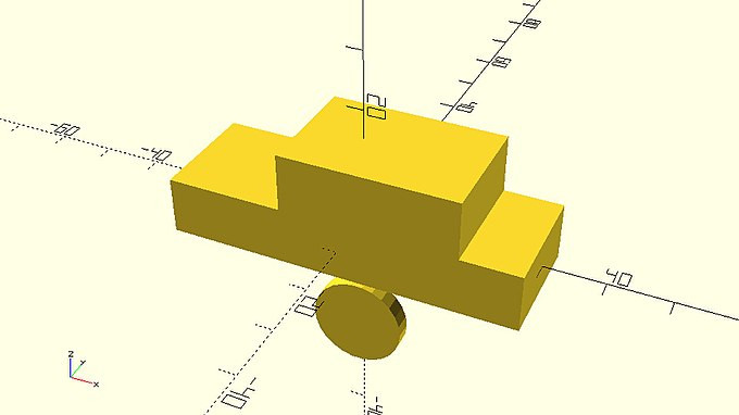
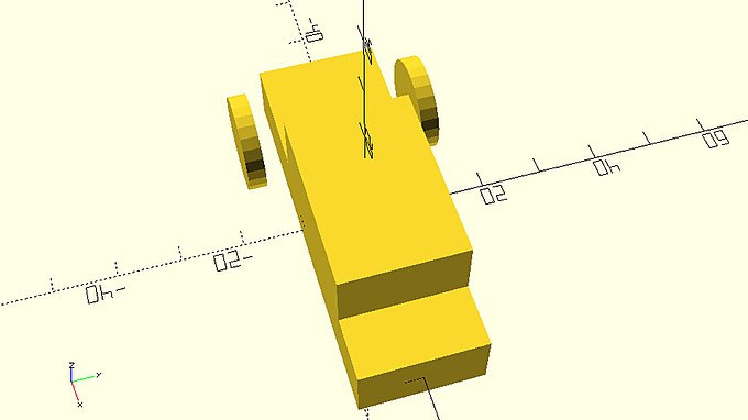
The third thing you should notice is that the wheel is standing straight but as a result of its rotation around the x axis it has moved below the car. This happened because the object was already moved away from the origin before it was rotated. A good practice for placing objects inside your model is first to rotate them and then to translate them to the desired position. Note that OpenSCAD generates the object, and then applies the object's transformations starting with the one immediately before the object definition and working backwards. So in order to rotate your object and then move it with a translation, specify the translation first in the code, followed by the rotation, followed by the object definition.
::第三个你应该注意到的是,轮子是直立的,但由于它在x轴周围的旋转,它已经移动在车子以下.这发生是因为对象在旋转之前已经从原点移开.将对象放置在模型中的一个好方法是首先旋转它们,然后将它们转换到所需位置.请注意,OpenSCAD生成对象,然后应用对象的转换,从对象定义前的转换开始,向后工作.所以为了旋转你的对象,然后用转换移动它,在代码中指定第一个转换,然后旋转,然后转换对象定义.
| Try first rotating the wheel and then translating it, by changing the order of the rotate and translate commands. |
|
two_cubes_and_a_rotated_and_translated_cylinder.scad
cube([60,20,10],center=true);
translate([5,0,10 - 0.001])
    cube([30,20,10],center=true);
translate([0,-20,0])
    rotate([90,0,0])
    cylinder(h=3,r=8);
|
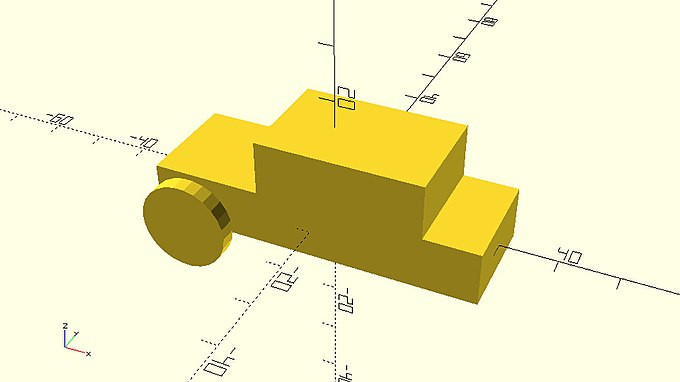
![]()
It already looks a lot better than the previous position of the wheel.
::现在的车轮位置已经比以前好了很多.
| Try modifying the input parameter of the translate command to make this wheel the front left wheel of your car. |
|
car_body_and_front_left_wheel.scad
cube([60,20,10],center=true);
translate([5,0,10 - 0.001])
    cube([30,20,10],center=true);
translate([-20,-15,0])
    rotate([90,0,0])
    cylinder(h=3,r=8);
|
| Try adding the front right wheel of the car by duplicating the last statement and changing only the sign of one value. |
|
car_body_and_misaligned_front_wheels.scad
cube([60,20,10],center=true);
translate([5,0,10 - 0.001])
    cube([30,20,10],center=true);
translate([-20,-15,0])
    rotate([90,0,0])
    cylinder(h=3,r=8);
translate([-20,15,0])
    rotate([90,0,0])
    cylinder(h=3,r=8);
|
You should notice that the position of the wheels is not symmetric. This happened because the cylinder was not created centered on the origin.
::您应该注意到轮子的位置不对称. 这是因为圆柱体不是以原点为中心而创建的.
| Try adding an additional input parameter to the cylinder commands to denote to OpenSCAD that both wheels should be centered on the origin when first created. Is the position of your wheels symmetric now? |
|
car_body_and_aligned_front_wheels.scad
cube([60,20,10],center=true);
translate([5,0,10 - 0.001])
    cube([30,20,10],center=true);
translate([-20,-15,0])
    rotate([90,0,0])
    cylinder(h=3,r=8,center=true);
translate([-20,15,0])
    rotate([90,0,0])
    cylinder(h=3,r=8,center=true);
|
Completing your first model
::完成你的第一个模型
| Try using what you have learned to add the rear missing wheels to the car. Try adding a connecting axle to the front and rear wheels. |
|
completed_car.scad
cube([60,20,10],center=true);
translate([5,0,10 - 0.001])
    cube([30,20,10],center=true);
translate([-20,-15,0])
    rotate([90,0,0])
    cylinder(h=3,r=8,center=true);
translate([-20,15,0])
    rotate([90,0,0])
    cylinder(h=3,r=8,center=true);
translate([20,-15,0])
    rotate([90,0,0])
    cylinder(h=3,r=8,center=true);
translate([20,15,0])
    rotate([90,0,0])
    cylinder(h=3,r=8,center=true);
translate([-20,0,0])
    rotate([90,0,0])
    cylinder(h=30,r=2,center=true);
translate([20,0,0])
    rotate([90,0,0])
    cylinder(h=30,r=2,center=true);
|
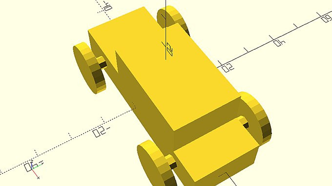
You should notice that on the model above there is an overlap between the axles and the wheels that is equal to half the thickness of the wheels. If the model was created in a way that the wheels and the axles were just touching each other then there would be a need to ensure a small overlap between them as was done with the two cubes of the car’s body.
::您应该注意到,在上面的模型中,轴和轮子之间存在重叠,其厚度等于轮子的一半.如果模型是以这样的方式创建的,轮子和轴只是互相触碰,那么就需要确保它们之间存在小的重叠,就像在车身的两个立方体上一样.
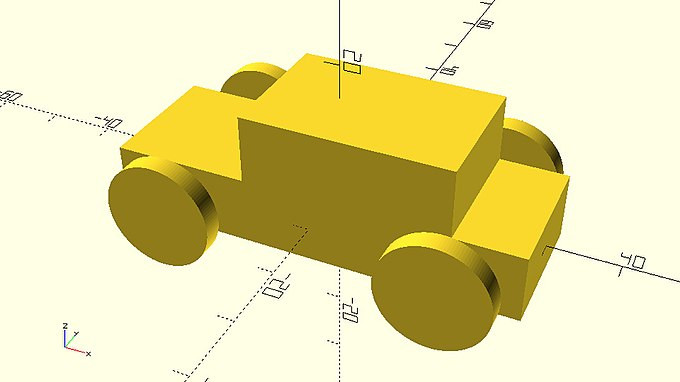
One thing that may have bothered you so far is the resolution of the wheels. Until now you have been using OpenSCAD’s default resolution settings. There are special commands in OpenSCAD language which allow you to have full control over the resolution of your models. Increasing the resolution of your model will also increase the required rendering time every time you update your design. For this reason, it is advised that you keep the default resolution settings when you are building your model and increase the resolution only after completing your design. Since the car example is completed, you can increase the resolution by adding the following two statements in your script.
::现在,你可能会对车轮的分辨率感到困扰.到目前为止,你一直使用OpenSCAD的默认分辨率设置.在OpenSCAD语言中,有特殊的命令允许你完全控制模型的分辨率.增加模型的分辨率也会增加每次更新设计时所需的染时间.因此,建议你在构建模型时保留默认分辨率设置,并在完成设计后增加分辨率.由于汽车示例已经完成,你可以通过在脚本中添加以下两个语句来增加分辨率.
$fa = 1; $fs = 0.4; |
Try adding the above two statements at the beginning of the car’s script. Do you notice any changes in the resolution of the wheels?
::试着在汽车的脚本开始时添加上述两个语句. 你是否注意到车轮分辨率有任何变化?
|
completed_car_higher_resolution.scad
$fa = 1;
$fs = 0.4;
cube([60,20,10],center=true);
translate([5,0,10 - 0.001])
    cube([30,20,10],center=true);
translate([-20,-15,0])
    rotate([90,0,0])
    cylinder(h=3,r=8,center=true);
translate([-20,15,0])
    rotate([90,0,0])
    cylinder(h=3,r=8,center=true);
translate([20,-15,0])
    rotate([90,0,0])
    cylinder(h=3,r=8,center=true);
translate([20,15,0])
    rotate([90,0,0])
    cylinder(h=3,r=8,center=true);
translate([-20,0,0])
    rotate([90,0,0])
    cylinder(h=30,r=2,center=true);
translate([20,0,0])
    rotate([90,0,0])
    cylinder(h=30,r=2,center=true);
|
In reality $fa and $fs are special variables that determine the resolution of the model according to the values that have been assigned to them. Their exact function will be explained later and is something that you should not worry about yet. The only thing you need to keep in mind is that you can add these two statements in any script to achieve a resolution that is universally good for 3D printing. These two statements will be used in all examples throughout the tutorial in order to have visually appealing renderings.
::实际上,$fa和$fs是根据它们所赋予的值来决定模型的分辨率的特殊变量.它们的确切功能将在稍后解释,这是你不应该担心的事情.你需要记住的唯一一件事是,你可以在任何脚本中添加这两个语句来实现对3D打印普遍好的分辨率.这两个语句将在整个教程中的所有示例中使用,以便具有视觉上有吸引力的染.
Before sharing your script with your friends, it would be nice to include some comments to help them understand your script. You can use a double slash at the start of a line to write anything you like without affecting your model. By using a double slash OpenSCAD knows that what follows is not part of the scripting language and simply ignores it.
::在与朋友分享脚本之前,很好添加一些评论来帮助他们理解脚本.你可以在一行开始使用双斜来写你喜欢的任何东西而不影响你的模型.通过使用双斜,OpenSCAD知道以下内容不是脚本语言的一部分,并且简单地忽略它.
| Try adding a comment above each statement to let your friends know what part of your model is created with each statement. |
$fs = 0.4;
// Car body base
cube([60,20,10],center=true);
// Car body top
translate([5,0,10 - 0.001])
cube([30,20,10],center=true);
// Front left wheel
translate([-20,-15,0])
rotate([90,0,0])
cylinder(h=3,r=8,center=true);
// Front right wheel
translate([-20,15,0])
rotate([90,0,0])
cylinder(h=3,r=8,center=true);
// Rear left wheel
translate([20,-15,0])
rotate([90,0,0])
cylinder(h=3,r=8,center=true);
// Rear right wheel
translate([20,15,0])
rotate([90,0,0])
cylinder(h=3,r=8,center=true);
// Front axle
translate([-20,0,0])
rotate([90,0,0])
cylinder(h=30,r=2,center=true);
// Rear axle
translate([20,0,0])
rotate([90,0,0])
cylinder(h=30,r=2,center=true);
It’s time to save your model. Hit the save (third) icon on the action bar above the editor to save your script as a *.scad file. When you are creating a new model remember to save early and then save often to avoid accidentally losing your work.
::现在是保存模型的时候了. 点击编辑器上方的动作上的保存 (第三) 图标以保存脚本为 *.scad 文件. 当您创建一个新模型时,请记住尽早保存,然后经常保存以避免意外丢失您的作品.
If you would like to 3D print your car you can export it as an STL file. You should first hit the render (second) icon on the action bar below the viewport to generate the STL data of your model. You should then hit the export as STL icon on the action bar above the editor to save a STL file of your model.
::如果您想3D打印汽车,可以将其导出为STL文件.您应该首先点击视图口下方的动作上的染 (第二) 图标以生成您的模型的STL数据.然后点击导出为STL图标在编辑器上方的动作上以保存您的模型的STL文件.
Creating a second model
::创建第二个模型
| Try using everything you learned to create a new simple model. It can be a house, an airplane or anything you like. Don’t worry about making your model look perfect, just experiment with your new skills! You will keep learning more techniques to create awesome models in the following chapters. |