OpenSCAD教程
Rotationally extruding 3D objects from 2D objects
::从二维物体旋转挤出3D物体
So far you have been creating a lot of models and customizing your car designs while developing solid parametric modelling skills and exploring different features of OpenSCAD. It’s quite impressive when you consider that every model you have created so far makes use of just three primitives: the sphere, the cube and the cylinder. By combining these primitives with the transformation commands you can create a plethora of models, but there are still models that can’t be created by using these primitives alone. One such example is the following wheel design.
::现在,你已经创建了很多模型,并定制了你的汽车设计,同时开发了坚实的参数建模技能,并探索了OpenSCAD的不同功能.当你考虑到你迄今为止创建的每个模型只使用了三个原始体:球体,立方体和圆柱体时,这非常令人印象深刻.通过将这些原始体与转换命令结合起来,你可以创建大量模型,但仍然有模型不能仅仅使用这些原始体来创建.以下的车轮设计就是一个例子.
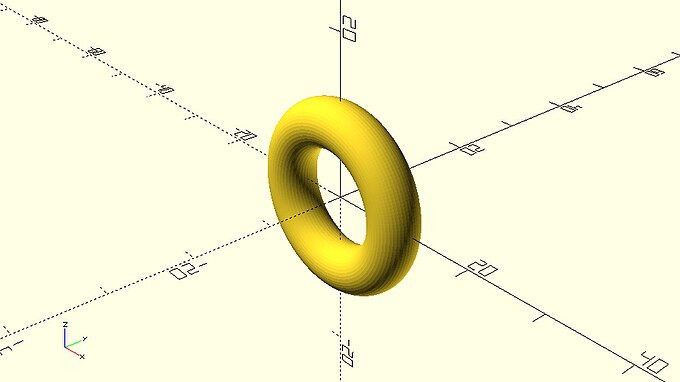
The above wheel design requires the creation of an object that looks like a donut.
::需要创造一个看起来像甜甜圈的物体.
This donut shaped object can’t be created with the use of the sphere, cube and cylinder primitives. Instead it requires the use of 2D primitives and a new command which can create 3D shapes from 2D profiles. Specifically, the donut can be created by first defining a circular 2D profile using the circle primitive and then rotationally extruding this profile using the rotate_extrude command.
::这种圆圈形的对象不能用球,立方体和圆柱体的原始创建.相反,它需要使用二维原始和一个新的命令,可以从二维配置文件中创建3D形状.具体来说,圆圈可以通过首先使用圆形原始定义一个圆形二维配置文件,然后使用rotate_extrude命令旋转挤出这个配置文件来创建圆圈.
|
circular_profile.scad
$fa = 1;
$fs = 0.4;
wheel_radius = 12;
tyre_diameter = 6;
translate([wheel_radius - tyre_diameter/2, 0])
    circle(d=tyre_diameter);
|
|
extruded_donut.scad
$fa = 1;
$fs = 0.4;
wheel_radius = 12;
tyre_diameter = 6;
rotate_extrude(angle=360) {
    translate([wheel_radius - tyre_diameter/2, 0])
        circle(d=tyre_diameter);
}
|
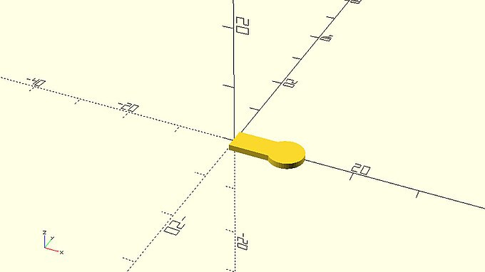
There are a few things you should notice about the 2D profile that you have created. In this case, the 2D profile is created using the circle command, and the diameter is set equal to the tyre_diameter variable. This was done because the donut-shaped object will correspond to the tyre of the wheel. Later on, you may discover other 2D primitives like the square command.
::关于你创建的二维配置文件,你应该注意到一些事情. 在这种情况下,二维配置文件是使用圆命令创建的,直径设置为与 tyre_diameter 变量相同. 这是因为甜甜圈形的对象将与轮子的轮胎对应. 后来,你可能会发现其他二维原始函数,如方形命令.
Any 2D profiles you plan to extrude should be created on the X-Y plane, and typically in the region where X is positive. Defined mathematically, 2D profiles usually reside where X ≥ 0, and Z = 0. Also, 2D profiles always have zero thickness. This means that 2D profiles are never used directly as a part of the model, but are instead used in conjunction with the rotate_extrude and linear_extrude commands to define 3D objects.
::您计划挤出的任何2D配置文件都应在X-Y平面上创建,通常在X为正的区域.数学定义,2D配置文件通常位于X ≥ 0和Z = 0.另外,2D配置文件总是具有零厚度.这意味着2D配置文件从未直接作为模型的一部分使用,而是与rotate_extrude和linear_extrude命令一起用于定义3D对象.
You should notice a few things about the use of the rotate_extrude command as well. The rotate extrude command is used to create 3D objects, and always requires a 2D profile as an input. The commands that create the desired 2D profile need to be placed inside the pair of curly brackets that follows the rotate_extrude command. The 3D object that is created by the rotate_extrude command is the result of rotating the 2D profile around the Y axis. The resulting 3D object is then placed so that its axis of rotation lies along the Z-axis. This quirk can take some getting used to at first, so it may help to review the process one step at a time.
::关于使用rotate_extrude命令,你也应该注意到一些事情.rotate_extrude命令用于创建3D对象,并且总是需要2D配置文件作为输入.创建所需的2D配置文件的命令需要放置在rotate_extrude命令后面的括号内. rotate_extrude命令创建的3D对象是将2D配置文件绕Y轴旋转的结果.然后,生成的3D对象将其旋转轴沿Z轴放置.这个奇特的东西可能需要一开始习惯,所以它可能有助于逐步审查这个过程.
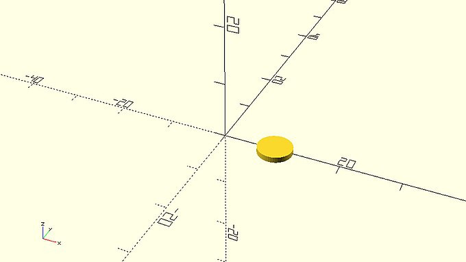
First, the rotate_extrude command takes a 2D profile as an input.
::首先,rotate_extrude命令将一个二维配置文件作为输入.

Then it creates a 3D object which is the result of rotating the supplied 2D profile around the Y axis.
::然后它创建一个3D对象, 这是旋转提供2D配置文件的结果,
Finally, it places the 3D model as if it were rotated by 90 degrees around the X axis. The result is that the Y axis which the model was revolved around has been rotated up to align with the Z axis.
::最后,它将3D模型放置在X轴周围,好像它被旋转了90度.结果是,模型旋转的Y轴已经被旋转到与Z轴对齐.

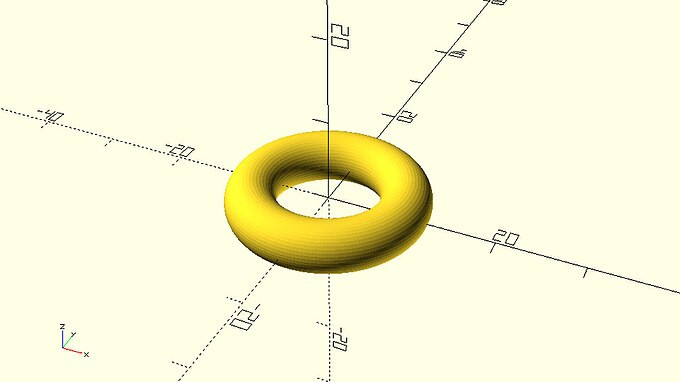
The rotate_extrude command has one input parameter named angle. The angle parameter is used to define how many degrees the 2D profile will be rotated around the Y axis. In this case the angle parameter is set equal to 360 degrees which corresponds to a full circle.
::旋转_挤出命令有一个输入参数,称为角度. 角度参数用于定义2D配置文件将在Y轴周围旋转多少度. 在这种情况下,角度参数设置为360度,这与一个完整的圆相对应.
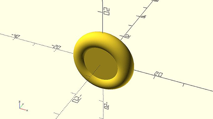
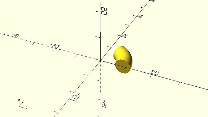
Setting the angle parameter equal to 60 degrees would create the following model.
::设置角度参数为 60 度会产生以下模型.
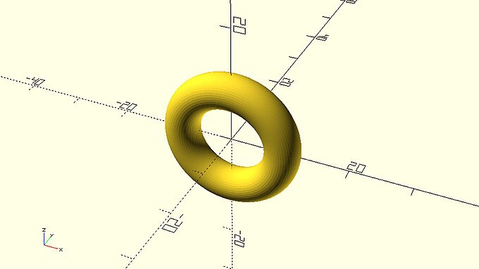
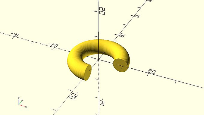
While setting it equal to 270 degrees would create the following one. And so forth.
::设置为270度会产生下一个.
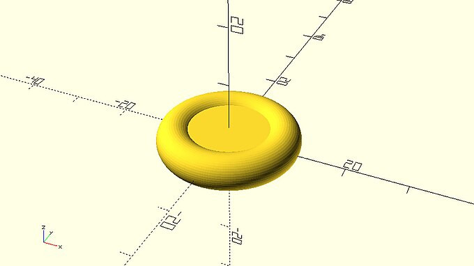
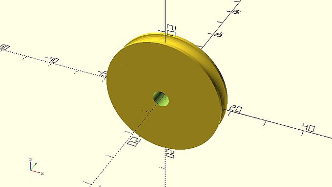
| Complete the new wheel design by defining the missing cylinder object. The height of the cylinder should be equal to the value of a wheel_width variable, while the radius of the cylinder should be equal to wheel_radius - tyre_diameter/2. The cylinder should be centred on the origin. |
|
rounded_wheel_horizontal.scad
$fa = 1;
$fs = 0.4;
wheel_radius = 12;
wheel_width = 4;
tyre_diameter = 6;
rotate_extrude(angle=360) {
    translate([wheel_radius-tyre_diameter/2,0])
        circle(d=tyre_diameter);
}
cylinder(h=wheel_width, r=wheel_radius - tyre_diameter/2, center=true);
|
| To make this wheel compatible with the models from the previous chapters rotate it by 90 degrees around the X axis. Turn this wheel design into a module named rounded_simple_wheel and add it on your vehicle_parts.scad script for later use. |
…
module rounded_simple_wheel(wheel_radius=12, wheel_width=4, tyre_diameter=6) {
    rotate([90,0,0]) {
        rotate_extrude(angle=360) {
            translate([wheel_radius-tyre_diameter/2,0])
                circle(d=tyre_diameter);
        }
        cylinder(h=wheel_width, r=wheel_radius - tyre_diameter/2, center=true);
    }
}
…
|

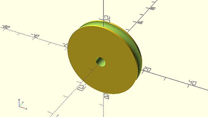
| The above wheel is an axisymmetric object, which means it exhibits symmetry around an axis. Specifically, the axis of symmetry is the axis around which the 2D profile was rotated to form the 3D object. When an object is axisymmetric it can be created with just one rotate_extrude command as long as the appropriate 2D profile is supplied. This is not the case with the above wheel design as the center part was added with a cylinder command separate from the rotational extrusion. Remove the cylinder command from the above module and make appropriate additions on the supplied 2D profile so that the whole wheel is created by the rotate_extrude command. |
…
translate([wheel_radius-tyre_diameter/2,0])
    circle(d=tyre_diameter);
translate([0,-wheel_width/2])
    square([wheel_radius-tyre_diameter/2,wheel_width]);
…
|

…
module rounded_simple_wheel(wheel_radius=12, wheel_width=4, tyre_diameter=6) {
    rotate([90,0,0]) {
        rotate_extrude(angle=360) {
            translate([wheel_radius-tyre_diameter/2,0])
                circle(d=tyre_diameter);
            translate([0,-wheel_width/2])
                square([wheel_radius-tyre_diameter/2,wheel_width]);
        }
    }
}
…
|
You should remember that axisymmetric objects can be completely created out of a rotate_extrude command. The previous wheel design is a concrete example of this. Whether you decide to create an axisymmetric object by supplying the 2D profile of the whole object and by using a single rotate_extrude or by using a rotate_extrude command only for its parts that can’t be created in any other way, depends on each case and is up to you. If you wanted for example to further modularize your wheel designs and separate them into combinable tire and rim modules, you would inevitably need to create the donut-shaped tire using a rotate_extrude command. Since in this case the rim of the wheel would be a separate module without a rotate_extrude command already present in it, the simplest and most straight forward way to create it would be by using a cylinder command.
::您应该记住,可以完全用 rotate_extrude 命令创建轴对称对象.前面的轮子设计就是一个具体的例子.无论您是决定通过提供整个对象的 2D 配置文件并使用单个 rotate_extrude 或仅使用 rotate_extrude 命令来创建其无法以任何其他方式创建的部分,这取决于每个情况下,取决于您.例如,如果您想进一步模块化您的轮子设计并将其分为可组合的轮胎和轮模块,您将不可避免地需要使用 rotate_extrude 命令创建圆圈形轮胎.由于在这种情况下,轮子的轮将是一个独立的模块,而没有 rotate_extrude 命令,所以使用直筒命令将是创建它的最简单和最前
Challenge
::挑战
It’s time to put your new knowledge into practice to create a rim for a mini robot car project.
::现在是时候将你的新知识付诸实践,
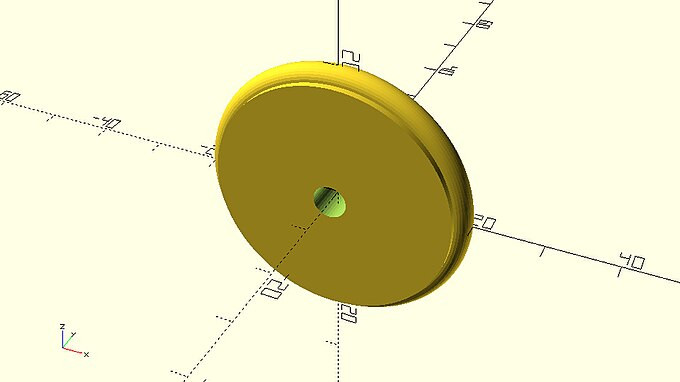
| Extend the rounded_simple_wheel module, so that the wheel design has a hole on its hub that can be used for mounting it on an axle. To do so you would need to subtract a cylinder from the existing model using a difference command. The diameter of the hole should be equal to a new module input parameter named axle_diameter. The default value of this parameter should be 3 units. By the way in which you define the height of the cylinder you should guarantee that the cylinder is always a bit longer than the width of the wheel to avoid any errors when using the difference command. After saving the modified module you should use it to create a version a wheel with wheel_radius, wheel_width, tire_diameter and axle_diameter of 20, 6, 4 and 5 units respectively. |
|
robot_wheel.scad
…
module rounded_simple_wheel(wheel_radius=12, wheel_width=4, tyre_diameter=6, axle_diameter=3) {
    difference() {

        // wheel
        rotate([90,0,0]) {
            rotate_extrude(angle=360) {
                translate([wheel_radius-tyre_diameter/2,0])
                    circle(d=tyre_diameter);
                translate([0,-wheel_width/2])
                    square([wheel_radius-tyre_diameter/2,wheel_width]);
            }
        }

        // axle hole
        rotate([90,0,0])
            cylinder(h=wheel_width+1,r=axle_diameter/2,center=true);
    }
}
…
|
… rounded_simple_wheel(wheel_radius=20, wheel_width=6, tyre_diameter=4, axle_diameter=5); … |
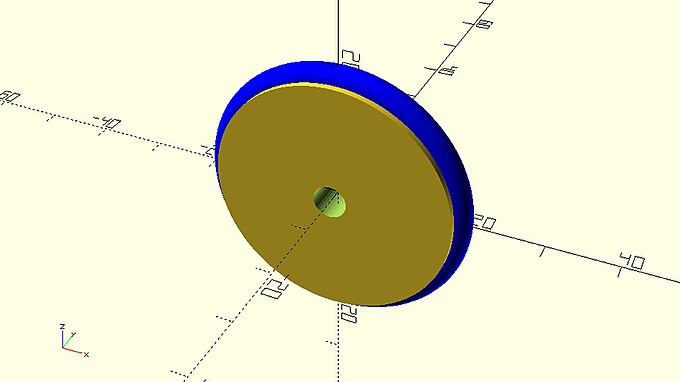
This wheel design looks about right for a mini robot car application, but you could do something to give more traction to your robot. Instead of 3D printing the whole wheel, you could just 3D print the rim and then add an O-ring or rubber band as the tire for more traction. The resulting wheel would look like the following image, where the O-ring or rubber band is represented by the blue color.
::这种轮子设计看起来适合小型机器人汽车应用,但你可以做一些让你的机器人有更多的引力.而不是3D打印整个轮子,你可以3D打印轮,然后添加一个O环或带作为轮胎,以获得更多的引力.结果的轮子看起来像下面的图像,其中O环或带用蓝色表示.
The corresponding rim that you would have to 3D print in this case is the following.
::您需要3D打印的相应边框是如下:
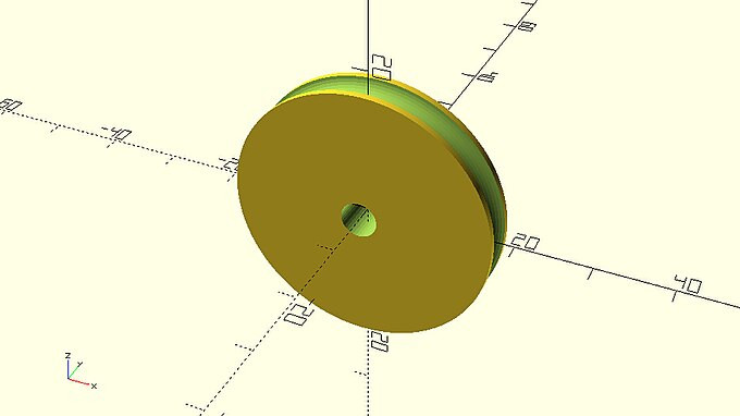
Using the rounded_simple_wheel module as a guide, create a new module named robot_rim. The robot_rim module should have the same input parameters as the rounded_simple_wheel module. Add all necessary commands to the robot_rim module so that it creates the above rim design. There are two ways in which you can do this.
|
-
First approach
::第一个方法
|
robot_rim_from_profile_difference.scad
…
module rounded_simple_wheel(wheel_radius=12, wheel_width=4, tyre_diameter=6, axle_diameter=3) {
    rotate([90,0,0])difference() {

        // resulting rim
        rotate_extrude(angle=360) {
            difference() {

                // cylindrical rim profile
                translate([0,-wheel_width/2])
                    square([wheel_radius-tyre_diameter/2,wheel_width]);

                // tire profile
                translate([wheel_radius-tyre_diameter/2,0])
                    circle(d=tyre_diameter);
            }
        }

        // axle hole
        cylinder(h=wheel_width+1,r=axle_diameter/2,center=true);
    }
}
…
|
-
Second approach
::第二种方法
|
robot_rim_from_3d_object_difference.scad
…
module rounded_simple_wheel(wheel_radius=12, wheel_width=4, tyre_diameter=6, axle_diameter=3) {
    rotate([90,0,0])
        difference() {

            // cylindrical rim
            cylinder(h=wheel_width,r=wheel_radius-tyre_diameter/2,center=true);

            // tire
            rotate_extrude(angle=360) {
                translate([wheel_radius-tyre_diameter/2,0])
                    circle(d=tyre_diameter);
            }

            // axle hole
            cylinder(h=wheel_width+1,r=axle_diameter/2,center=true);
        }
}
…
|
Often, it's helpful to consider the manufacturing process that will be used in an object's creation when designing a new part. Usually, this consideration promotes designs that accommodate the manufacturing method at hand, but it can guide your modeling process as well.
::通常,在设计新零件时,考虑将用于物体创建的制造过程是有帮助的.通常,这种考虑促进了适应手头制造方法的设计,但它也可以指导您的建模过程.
For example, consider a scenario where instead of using additive manufacturing like 3D printing to manufacture this robot wheel, you used subtractive manufacturing like lathe or a mill. In this case you might opt to use the second approach, since it would more closely replicate the manufacturing process at hand, and could give you a better estimate of how many steps the final manufacturing process might take.
::例如,考虑一个场景,即使用增材制造,如3D打印制造这个机器人轮子,而不是使用减法制造,如轮或磨机. 在这种情况下,您可能会选择使用第二种方法,因为它会更接近复制手头的制造过程,并可以给你一个更好的估计最终制造过程可能需要多少步骤.
Linearly extruding 3D objects from 2D objects
::从二维物体线性挤出3D物体
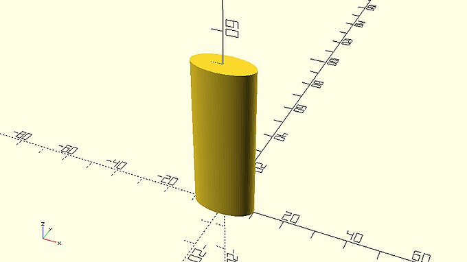
As briefly mentioned, there is another OpenSCAD command that can be used to create 3D objects from supplied 2D profiles. This is the linear_extrude command. In contrast to the rotate_extrude command, linear_extrude creates a 3D object by extending along the Z axis a 2D profile that lies on the XY plane. Similar to the rotate_extrude command, linear_extrude can be used when the 3D object you want to create can’t be directly created by combining available 3D primitives. One such example is the following.
::简要地说,还有另一个 OpenSCAD 命令可以用来从提供的 2D 配置文件中创建 3D 对象.这是线性_挤出命令.与旋转_挤出命令不同,线性_挤出命令通过沿 Z 轴延伸位于 XY 平面上的 2D 配置文件来创建 3D 对象.类似于旋转_挤出命令,线性_挤出可以在您想要创建的 3D 对象无法通过组合可用的 3D 原始体直接创建时使用.以下是一个这样的例子.
|
extruded_ellipse.scad
$fa = 1;
$fs = 0.4;
linear_extrude(height=50)
    scale([2,1,1])
    circle(d=10);
|
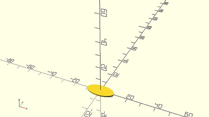
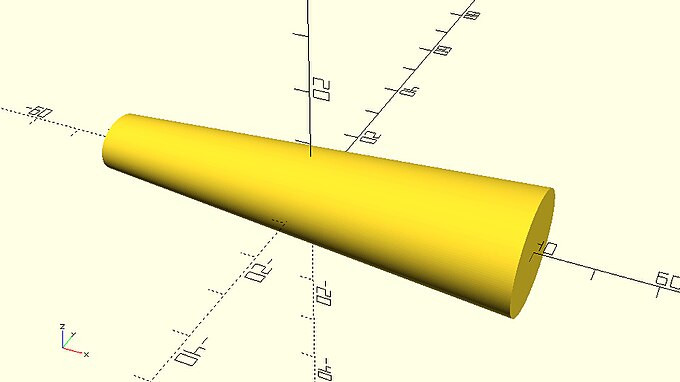
The above object is a tube that has the following profile.
::上面的物体是一个具有以下形状的管.
|
ellipse_profile.scad
$fa = 1;
$fs = 0.4;
scale([2,1,1])
    circle(d=10);
|
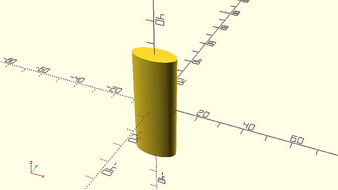
There are a few points you should notice regarding the use of linear_extrude. The syntax of linear_extrude is similar to the syntax of the rotate_extrude command. The commands that create the 2D profile that will be extruded along the Z axis need to be placed inside a pair of curly brackets that follows the linear_extrude command. The parameter height is used to define how many units along the Z axis the 2D profile is going to be extruded. By default, the 2D profile is extruded along the positive direction of the Z axis by an amount of units equal to the value assigned to the height parameter.
::关于使用linear_extrude,你应该注意一些点.linear_extrude的语法与rotate_extrude命令的语法相似.将在Z轴上挤出的2D配置文件的命令需要放置在一个跟着linear_extrude命令的括号内.参数高度用于定义2D配置文件将在Z轴上挤出多少单位.默认情况下,2D配置文件将在Z轴的正方向上挤出与高度参数赋值相同的单位数量.
By passing an additional parameter named center and setting it equal to true, the 2D profile is extruded along both directions of the Z axis. The total length of the resulting object will still be equal to the height parameter.
::通过通过一个额外的参数,即中心,并将其设置为真,将2D配置文件沿 Z 轴的两个方向挤出. 结果的对象的总长度仍然等于高度参数.
|
centered_extrusion.scad
…
linear_extrude(height=50,center=true)
    scale([2,1,1])
    circle(d=10);
…
|
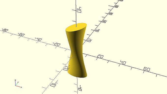
An additional parameter named twist can also be used to twist the resulting 3D object around the Z axis by the specified angle.
::另外一个叫做twist的参数也可以用来在Z轴周围以指定角度扭转得到的3D对象.
|
extrusion_with_twist.scad
…
linear_extrude(height=50,center=true,twist=120)
    scale([2,1,1])
    circle(d=10);
…
|
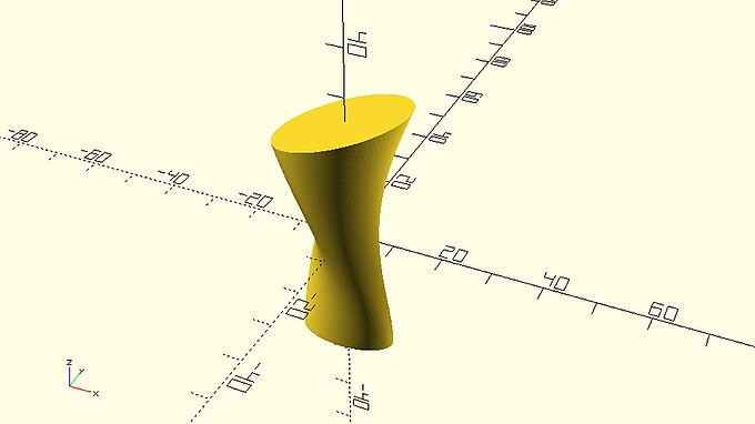
Finally, another parameter named scale can be used to scale one end of the resulting 3D by the specified scaling factor.
::最后,还有一个叫做尺度的参数可以用指定的缩放因子来缩放生成的3D的某端.
|
extrusion_with_twist_and_scale.scad
…
linear_extrude(height=50,center=true,twist=120,scale=1.5)
    scale([2,1,1])
    circle(d=10);
…
|
It should be pretty clear by now how the rotate_extrude and linear_extrude commands give you the ability to create objects that wouldn’t be possible by directly combining the available 3D primitives. You can use these commands to create more abstract and artistic designs but let’s see how you could use the linear_extrude command to create a new car body.
::现在应该很清楚,rotate_extrude和linear_extrude命令如何让你能够创建无法直接结合现有的3D原始体的对象.你可以使用这些命令来创建更抽象和艺术的设计,但让我们看看你如何使用linear_extrude命令来创建一个新的汽车车身.
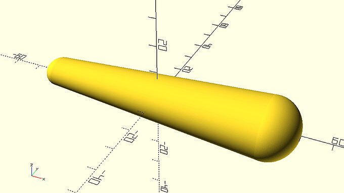
| Use the linear_extrude command similar to the above examples in order to create the following car body. You should create a new module named extruded_car_body. The module should have a length, rear_height, rear_width and scaling_factor input parameter. The default values of the parameters should be 80, 20, 25 and 0.5 units respectively. The length and scaling factor parameters of the module will be used in the call to linear_extrude command to set the values of its height and scale parameters. The supplied 2D profile should be a circle that has been resized according to the rear_height and rear_width parameters. |
|
extruded_car_body.scad
module rounded_car_body(length=80, rear_height=20, rear_width=25, scaling_factor=0.5) {
rotate([0,-90,0])
    linear_extrude(height=length,center=true,scale=scaling_factor)
    resize([rear_height,rear_width])
    circle(d=rear_height);
}
|
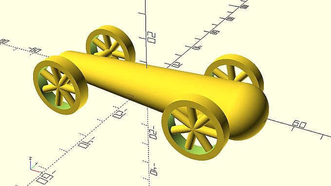
| Extend the previous module by adding a boolean input parameter named rounded. The default value of the parameter should be false. If the rounded parameter is set to true, then two additional objects should be created at the front and rear of the body in order to make in rounded as in the following image. These two objects are spheres that have been resized and scaled. Try figuring out an appropriate way to resize and scale the sphere to achieve a result similar to the image below. |
|
rounded_extruded_car_body.scad
…
module rounded_car_body(length=80, rear_height=20, rear_width=25, scaling_factor=0.5, rounded=false) {

    // center part
    rotate([0,-90,0])
        linear_extrude(height=length,center=true,scale=scaling_factor)
        resize([rear_height,rear_width])
        circle(d=rear_height);

    if (rounded) {
        // rear part
        translate([length/2,0,0])
            resize([rear_height,rear_width,rear_height])
            sphere(d=rear_height);

        // front part
        translate([-length/2,0,0])
            scale(scaling_factor)
            resize([rear_height,rear_width,rear_height])
            sphere(d=rear_height);
    }
}
…
|
| Use the new rounded body in any car design that you like. |
As mentioned, the rotate_extrude and linear_extrude commands can also be used to create more abstract objects. When the supplied 2D profile is created using the available circle and square 2D primitives and when the twist and scale parameters of the linear_extrude command are not utilized, then the resulting 3D object could also be directly created using the available 3D primitives. What really makes the use of these commands much more powerful is the ability to create any 2D profile that is not a combination of circles and squares but rather an arbitrary shape. This ability is available through the use of the polygon 2D primitive which you are going to learn about in the next chapter.
::如前所述,rotate_extrude和linear_extrude命令也可以用来创建更抽象的对象.当使用可用的圆和方形2D原始体创建所提供的2D配置文件,并且当不使用linear_extrude命令的扭转和缩放参数时,则使用可用的3D原始体直接创建所得到的3D对象.真正使这些命令的使用更强大的是能够创建任何2D配置文件,而不是圆和方形的组合,而是任意的形状.这种能力可以通过使用多边形2D原始体,您将在下一章中了解.