Blender 3D:零基础到专业级-单元2:基本建模和着色
A mesh is one of the most important and frequently-used object types in Blender. While there are other types of objects that can be used to model parts of a model or scene (text, NURBS patches, etc.), they often get converted to meshes at some point anyway, because it is the object type that offers the greatest amount of detailed control. And as it happens, Blender offers more functions, both built-in and available as addons, for dealing with meshes than for any other object type.
::网格是Blender中最重要和最常用的对象类型之一.虽然有其他类型的对象可以用于模拟模型或场景的部分 (文本,NURBS补丁等),但它们通常在某个时候被转换为网格,因为它是提供最大程度的详细控制的对象类型.而且,由于如此,Blender提供了更多的功能,既内置,又可作为附加功能,用于处理网格,而不是任何其他对象类型.
Edit mode is the mode in which you make changes to the internals of the
active
object. Not every object has an Edit mode (e.g. cameras), and the details of what you can do in Edit mode vary between the object types where it is available. This module specifically covers Edit mode for mesh objects.
::编辑模式是您对活动对象内部进行更改的模式.并非每个对象都有编辑模式 (例如摄像机),并且您可以在编辑模式中做的事情的细节在可用的对象类型之间有所不同.此模块专门涵盖网格对象的编辑模式.
What Is a Mesh?
什么是网格?
A
mesh
is made up of one or more
vertices
; each
vertex
is just a point in space. A pair of vertices can be joined by a straight line called an
edge
, and a complete loop of edges can be filled in to form a
face
.
::网状网由一个或多个顶点组成;每个顶点只是一个空间点.一对顶点可以通过一条称为边缘的直线连接,并且可以填充一条完整的边缘循环以形成面.
It is the faces that make up the visible surface of the object. The edges and vertices are essentially geometrical "scaffolding" necessary to hold the object together.
::表面是物体的可见表面.边缘和顶点基本上是为了保持物体的整体而需要的几何"脚手架".
A face must have three or more sides (edges). Prior to version 2.63, only three or four sides were allowed, so faces had to be
triangles
or
quadrilaterals
(usually abbreviated to
quads
) respectively. Starting with v2.63, and the introduction of the BMesh architecture, that restriction has been lifted. You can have faces with 5 or more sides, but you will usually find that things work best if all faces, as far as possible, are quads. Particularly when constructing a model for animation purposes.
::面必须有三面或更多面 (边). 在2.63版本之前,只允许三面或四面,因此面必须分别是三角形或四边形 (通常缩写为四边形). 从v2.63开始,以及BMesh架构的引入,这一限制已经被取消.你可以有5个或更多面,但你通常会发现,如果所有面尽可能都是四边形,事情会最好地运行. 特别是当构建模型用于动画目的时.
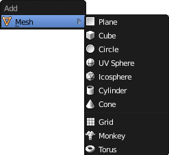
Blender’s Object-mode “Add” menu ( SHIFT + A ) contains a Mesh submenu with a collection of pre-made mesh objects. Think of these as starting points. They make building your own objects easier by enabling you to modify an object that is an approximation of the form you want instead of having to construct a mesh entirely from scratch.
::混合器的对象模式的添加菜单 (SHIFT + A) 包含一个 Mesh 子菜单,其中包含一系列预制的网格对象.把它们看作是起点.它们使您可以更轻松地构建自己的对象,使您能够修改一个对象,它是您想要的形式的近似,而不是从头开始构建一个网格.
Introduction to Edit Mode
编辑模式简介
Start a new model. Hide the manipulator if it is visible ( CTRL + SPACE ). You should be in Object mode. Click with RMB on the default cube to ensure it is selected and the active object.
::启动一个新模型. 如果操作器可见,请隐藏 (CTRL + SPACE). 您应该处于对象模式. 在默认立方体上点击RMB以确保选择和活动对象.
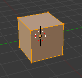
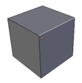
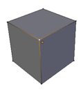
You can switch modes using the mode menu, as you previously learned. However, because switching between Object mode and Edit mode is such a frequent operation, it has a keyboard shortcut: TAB . Do this now, and you should see the appearance of the cube change, as shown at right. The mode menu should also update. Press TAB again, and you should be back in Object mode. Press TAB once more before continuing, to ensure you are in Edit mode.
::您可以使用模式菜单切换模式,正如您之前所学到的.但是,由于在对象模式和编辑模式之间切换是如此频繁的操作,它有一个键盘快捷键:TAB.现在这样做,您应该看到立方体的变化,如右图所示.模式菜单也应该更新.再次按TAB,您应该回到对象模式.在继续之前,再次按TAB,以确保您处于编辑模式.
Note the following features of the cube, and how they relate to the description of a mesh above:
::需要注意的是,立方体的以下特征和它们与上面描述的网格有何关系:
-
The dots at the corners are the vertices.
::角落上的点是顶点. -
The lines joining them are the edges.
::它们的连接线是边缘. -
The filled areas bordered by the lines are the faces.
::填充区域与线条相接,是面部.
Selection Modes
选择模式

In Edit mode, the header (it's at the top) of the 3D View window changes to show the selection-mode controls. If you hover over each of the buttons in the group of three, you will see they represent vertex-select, edge-select and face-select respectively. You can shift-click to enable more than one at a time.
::在编辑模式下,3D视图窗口的标题 (它位于顶部) 改变以显示选择模式控件.如果您在三组中的每个按上滑动,您将看到它们分别代表顶点选择,边缘选择和面部选择.您可以移动点击一次启用多个.
In vertex-select mode, you select a single vertex by clicking on it with RMB , and select more than one by shift-clicking on additional vertices with RMB . Shift-clicking with RMB on an already-selected vertex will deselect it.
::在顶点选择模式中,您可以通过使用人民币点击单个顶点,并通过使用人民币点击额外的顶点移动点击多个顶点进行选择.在已经选择的顶点上使用人民币移动点击将取消选择.
Pressing A will select
all
vertices if none are currently selected, otherwise it will
unselect
all vertices.
::如果没有选择, 按A将选择所有顶点, 否则将取消选择所有顶点.
Edge-select mode works in a similar way, except with edges instead of vertices. Similarly, face-select mode will allow you to select and unselect faces.
::边缘选择模式以类似的方式工作,但边缘不是顶点.同样,面部选择模式允许您选择和取消面部选择.
The single button immediately to the right of these three is titled “limit selection to visible”. When it is active (the default), the mesh object being edited is displayed as
opaque
which means that vertices, edges or faces on the side away from you are hidden and cannot be selected. Click this button, and the object becomes translucent, allowing clicking
through
front faces to select parts of the mesh behind them.
::在这三个选项中,右边的单个按是"限制选择可见".当它被激活 (默认),正在编辑的网格对象将显示为不透明,这意味着远离您的侧面的顶点,边缘或面部是隐藏的,无法选择.点击此按,对象将变得半透明,允许点击前面面部,选择它们后面的网格部分.
Another useful display mode for working in the 3D view is wireframe, which can be selected from the Viewport Shading menu or toggled with the Z key. In this mode, the faces become transparent, almost invisible, and the edges and vertices are displayed more prominently.
::另一个有用的显示模式是线框,可以从视图窗口遮菜单中选择或使用Z键切换.在这种模式下,面部变得透明,几乎看不见,边缘和顶点显示得更突出.
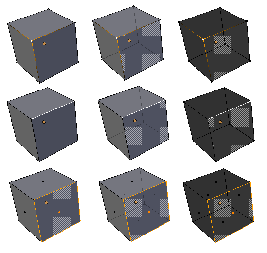
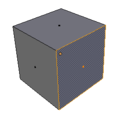
Here is what these various selection and display modes look like in combination: in the first row, a single vertex is selected. In the second row, a single edge, and in the third row, a single face. In the first column, limit-selection-to-visible is enabled. In the second column, it is disabled, and in the third column, wireframe mode is enabled.
::这里是这些不同的选择和显示模式组合的样子:在第一行中,选择一个单一的顶点.在第二行中,选择一个单一的边缘,在第三行中,选择一个单一的面.在第一列中,启用限制选择到可见.在第二列中,它是禁用,在第三列中,启用线框模式.在第一个列中,选择一个单一的边缘,在第三列中,选择一个单一的面.在第一个列中,选择一个单一的边缘,在第三列中,选择一个单一的面.在第一个列中,选择一个单一的边缘,在第三列中,选择一个单一的面.在第一个列中,选择一个单一的边缘,在第三列中,选择一个单一的面,在第三列中,选择一个
Selection Mode Hotkeys
::选择模式的快速键
You can also switch selection modes with CTRL + TAB . In the menu that appears, you can switch to a single selection mode by selecting it with the mouse or up/down-arrow keys and pressing ENTER or LMB . But if you press SHIFT + ENTER or SHIFT + LMB that toggles the enabling of only that selection mode, without affecting the state of the others, as does shift-clicking on the icons above.
::您还可以使用CTRL+TAB切换选择模式. 在显示的菜单中,您可以通过鼠标或上/下箭头键选择单个选择模式,并按ENTER或LMB. 但是如果您按SHIFT+ENTER或SHIFT+LMB,则只能切换该选择模式,而不会影响其他模式的状态,而按转移点击上面的图标也可以.
In common with other Blender popup menus, you can quickly select an item from the CTRL + TAB menu and immediately confirm by pressing one of 1KEY , 2KEY or 3KEY to select the first (vertex), second (edge) or third (face) item in the menu. Or, SHIFT + 1KEY , SHIFT + 2KEY and SHIFT + 3KEY while the menu is up, will toggle the enabling of vertex, edge, and face-select modes respectively.
::与其他 Blender 弹出菜单一样,您可以快速选择 CTRL + TAB 菜单中的项目,并通过按一键,二键或三键即可确认,选择菜单中的第一个 (顶部),第二个 (边缘) 或第三个 (面部) 项目. 或者,在菜单打开时,SHIFT + 1KEY,SHIFT + 2KEY 和 SHIFT + 3KEY 将分别切换顶部,边缘和面部选择模式.
Multiple Selections
多重选择
You can use SHIFT + RMB to select multiple items, and CTRL + I to invert the selection, just like in Object mode. Only here, the “items” are vertices, edges or faces, depending on the selection mode in effect. The active (last-selected) part is shown in white, while the rest of the selection (if any) is drawn in the usual orange-yellow colour.
::您可以使用SHIFT+RMB选择多个项目,并使用CTRL+I反转选择,就像在Object模式一样.只有在这里,项目是顶点,边缘或面部,取决于有效的选择模式.活动 (最后选择) 部分以白色显示,而其余的选择 (如果有的话) 则以通常的黄色颜色绘制.
As mentioned above, A works similar to the way it works in Object mode, only instead of applying to everything, it applies to all parts of the object being edited.
::如上所述,A 工作方式与 Object 模式类似,只是它不适用于所有内容,而是适用于正在编辑的对象的所有部分.
Hiding Things
藏物体
H , SHIFT + H and ALT + H work in a way analogous to their behaviour in Object mode. Again, instead of applying to everything, they apply to all parts of the object being edited.
::H,SHIFT + H和ALT + H的运作方式与它们在Object模式中的运作方式类似.再次,它们不适用于所有内容,而是适用于正在编辑的对象的所有部分.
Remembering What's Hidden:
If you switch out of Edit mode with some parts hidden, they will reappear, then disappear again when you re-enter Edit mode, i.e. each object remembers what was hidden when you last edited it.
::记住隐藏的内容:如果您在编辑模式中关闭某些部分,它们将再次出现,然后在重新进入编辑模式时再次消失,即每个对象都记得您上次编辑时隐藏的内容.
Local Versus Global View
局部视角与全局视角
You can toggle local/global view in Edit mode, as you can in Object mode. However, instead of narrowing the view to one or more selected objects, it narrows it to just the object being edited.
::您可以在编辑模式中切换本地/全球视图,就像在对象模式中一样. 然而,它不会将视图缩小到一个或多个选定的对象,而是将其缩小到仅仅正在编辑的对象.
Border Select (Box Selection) & Circle Select (Brush Selection)
边框选择(方框选择)和圆圈选择(笔刷选择)
B and C work analogously to the way they do in Object mode, i.e. you select multiple items by drawing a box or by “painting” over them.
::选择多个项目是通过画一个框或通过"涂上"它们.
Select More, Select Less
选择更多,选择更少
Edit mode has some additional selection capabilities. To demonstrate them, let’s use something other than the default cube, for a change. TAB back to Object mode, and delete the cube. Now add ( SHIFT + A ) a Grid object. TAB into Edit mode, and you will see that the grid is made up of 9×9 faces, or 10×10 vertices. Initially they will all be selected. Use A to unselect them then C to brush-select a few vertices in the middle. End brush-select mode with RMB or ESC . Now watch what happens to the selection when you press CTRL + NUM+ (select more). Additional vertices adjacent to those already selected are added to the selection. Now try CTRL + NUM− (select less), and you will see the vertices on the edge of the selection are removed from it.
::编辑模式有一些额外的选择功能.为了展示它们,让我们使用除了默认立方体之外的其他东西来进行改变. 返回对象模式,并删除立方体. 现在添加 (SHIFT + A) 网格对象. 进入编辑模式,您将看到网格由9×9面或10×10顶点组成. 起初它们都将被选择. 使用A来取消选择它们然后C来刷选中间的几个顶点. 用RMB或ESC结束刷选模式. 现在看看按Ctrl+NUM+ (选择更多) 时选择会发生什么. 添加到已经选择的边缘的额外的顶点被添加到选择中. 现在尝试Ctrl+NUM− (选择更少),您将看到选择边缘的顶点被删
Manipulator, Transformation Hotkeys, Pivot Point
机械手,变换热键,枢轴点
All of these are available for use in Edit mode as they are in Object mode, except for the “Manipulate center points” button.
::所有这些都可以在编辑模式下使用,因为它们在对象模式中,除了"操作中心点"按.
Note that scaling vertices scales the distances between them. The vertices themselves have no size, so they do not get larger or smaller. Similarly, rotating vertices only changes their direction relative to the pivot point, since a featureless point itself has no orientation.
::注意,缩放顶点缩放它们之间的距离.顶点本身没有尺寸,所以它们不会变大或变小.同样,旋转顶点只会改变它们相对于转点的方向,因为一个没有特征的点本身没有方向.
Transform Orientations
::转换方向
The Global, Local and View options in the Transform Orientation menu apply in Mesh Edit mode as they do in Object mode. In addition there is Normal mode, where the transformation axes are aligned relative to the selection:
::在转换定向菜单中的全球,本地和视图选项在网格编辑模式中与对象模式一样适用.此外还有正常模式,其中转换轴与选择相对对齐:
-
If a single face is selected, the X and Y axes are aligned along the face, while the Z axis is aligned perpendicular (normal) to the face.
::如果选择单一面,X和Y轴沿面对齐,Z轴则对齐垂直 (正常) 于面. -
If a single edge is selected, the Z axis is aligned along the edge, with the X and Y axes perpendicular to it.
::如果选择一个边缘,Z轴沿边缘对齐,X和Y轴垂直于边缘.
Other selections are also possible. Feel free to investigate their behaviour for yourself.
::其他选择也可能.请随时自己调查他们的行为.
Thus, with a single face selected, G Z Z will move the face along its normal.
::因此,只要选择一个面,GZZ将将面沿着正常的方向移动.
In addition, it is possible to define the current Normal transformation orientation as a custom orientation for use in transforming other vertices and even other objects. To do this, you need to go to the Properties Shelf, which is made visible on the right of the 3D view with N . Near the bottom is the Transform Orientations panel which contains a Transform Orientation menu which looks the same as the one in the header of the 3D View window, except it also has a “+” button next to it. Click the "+" and the current Normal transformation orientation will be added to the menu initially labeled “Vertex”, “Edge” or “Face”, depending on what is currently selected (and with a unique numeric suffix added if there is already a custom orientation defined with that name). Now if you look in either Transform Orientation menu, you will see a new selectable item, in a separate section above the five standard items.
::此外,还可以将当前的正常转换方向定义为用于转换其他顶点甚至其他对象的自定义方向.为了做到这一点,您需要进入属性架,该架在3D视图右侧以N为可见.在底部附近是转换方向面板,该面板包含一个转换方向菜单,看起来与3D视图窗口头部的菜单相同,但它旁边还有一个+按.点击"+"和当前的正常转换方向将被添加到最初标记为"顶部","边缘"或"面部"的菜单中,根据当前所选的 (并且根据已经添加了这个名字的自定义方向),现在,如果您在转换方向菜单中查看,您将在上面的标准部分看到一个新的可选择项,在一个
With your new orientation option selected, an editable text field will appear in the Transform Orientations panel, allowing you to change the name if you wish, and there is also a “X” button allowing you to delete the orientation item when you no longer need it.
::选择了新的方向选项, 转换方向面板中会出现一个可编辑的文本字段, 允许您更改名称, 如果您愿意, 还有一个X按, 允许您删除方向项目当您不再需要它.
With your new orientation option selected, you can now select a different part of the object, or even TAB into Object mode and select some other object. The manipulator and the doubled axis hotkeys will now align their transformations along this custom orientation. This is handy, for example, for aligning objects to a sloping plane.
::选择了新的定向选项,您现在可以选择对象的不同部分,甚至可以将TAB转换为对象模式并选择其他对象. 操纵器和双轴快捷键现在将它们的转换沿着这个自定义定向对齐. 这很方便,例如,对对象对齐到斜面.
Proportional Editing
成比例的编辑
When trying to produce natural, organic shapes, moving vertices one by one gets tedious. To produce smoother looking shapes, you need a mode where unselected vertices close to the selection also get some movement. In contrast to the sharp distinction between selected vertices which are moved and unselected ones that remain in place, there is a gradual transition from one to the other.
::试图产生自然的,有机的形状时,将顶点逐一移动变得乏味.为了产生更光滑的形状,你需要一种模式,在选择附近的未选顶点也会获得一些运动.与被移动的选顶点和未选顶点之间存在的明显区别相反,从一个到另一个的逐渐过渡.
This is where proportional editing comes in. If you select “Mesh” in the header and examine the pop-up menu, you will see two submenus, titled “Proportional Editing” and “Proportional Editing Falloff”. The former toggles the mode on and off, the latter controls the falloff function choice. There is also an icon for “Proportional Editing” in the header of the default 3D view. Look to the right of the "Limit Selection to Visible" (on edit mode). The hot key is the letter O. Pressing O will toggle between Enable and Disable. Pressing SHIFT + O will change the Falloff type.
::这就是比例编辑的作用.如果您在头部选择Mesh并检查弹出菜单,您将看到两个子菜单,标题为Proportional Editing和Proportional Editing Falloff.前者可以开启和关闭模式,后者可以控制掉落功能选择.默认3D视图的头部还有一个"比例编辑"的图标.请看"将选择限制为可见" (编辑模式).热键是O字母.按O将在Enable和Disable之间切换.按SHIFT+O将改变掉落类型.
The “Proportional Editing” submenu has 4 options: “Disable”, “Enable”, “Projected (2D)”, and “Connected”. Do you still have the Grid object you created in the “Select More, Select Less” section above? If not, add a fresh Grid object. Switch to Edit mode, and ensure that just a few vertices in the middle are selected. Enable proportional editing, and now use G to move the selected vertices. You should notice 2 things:
::比例编辑子菜单有4个选项:禁用,启用,投影 (2D) ,和连接.你是否仍然在上面的"选择更多,选择少"部分创建的网格对象?如果没有,请添加一个新的网格对象.切换到编辑模式,并确保只选择中间的几个顶点.启用比例编辑,现在使用G移动选定的顶点.你应该注意到2件事:
-
unselected vertices near the selected ones also move, and
::选择的顶点附近的未选的顶点也会移动,并且 -
there is a white circle enclosing all the vertices that undergo any movement.
::一个白色的圆圈包围着所有经历任何运动的顶点.
Try using the mouse wheel while moving the vertices, and you will see the white circle grow or shrink, and the proportional region of influence will grow or shrink correspondingly.
::试着在移动顶点时使用鼠标轮, 你会看到白色圆形会增大或缩小,
Try different falloff functions in the “Proportional Editing Falloff” submenu. Some ensure the mesh stays smooth and curvy, others give a more angular effect, etc.
::在"比例编辑"子菜单中尝试不同的落下功能.有些确保网格保持光滑和曲线,其他则提供更角的效果等.
The third option to "Disable" and "Enable" proportional editing is "Projected (2D)". This view is similar to enabled, except depth is ignored. The radius of the influence region is applied to the mesh two dimensionally.
::"禁用"和"启用"比例编辑的第三个选项是"投影 (2D)".这个视图类似于启用,但忽略了深度.影响区域的半径被应用到二维网格.
The fourth option to “Disable” and “Enable” proportional editing is “Connected”. This one makes a difference in more complicated meshes, which might have folds or concavities in them. In this situation, “Enable” affects all vertices within a particular distance of the selected ones, while “Connected” only measures the distance
via connected edges
, rather than directly through space. This lets you move one part of the mesh without affecting another part which might be located nearby purely as a result of a fold.
::禁用和启用比例编辑的第四个选项是连接. 这种选项在更复杂的网格中产生了区别,可能会有折叠或. 在这种情况下,启用会影响选定的特定距离内的所有顶点,而连接只通过连接边缘测量距离,而不是直接通过空间. 这让您移动网格的一部分,而不会影响其他部分,这些部分可能仅仅是由于折叠而位于附近.
Of course, proportional editing works with scale S and rotate R operations as well.
::当然,比例编辑也可以使用S尺度和R旋转操作.
Deleting Things
删除物体
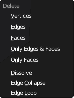
Now let’s try deleting parts of a mesh. This is the menu that comes up when you press X or DEL when editing a mesh. For now, we will concentrate on the first three items.
::现在让我们尝试删除网格的部分. 这是一个菜单,当你在编辑网格时按下X或DEL时会出现. 现在,我们将专注于前三项.
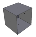
First, go into face-select mode. Select one face of the default cube, press the delete key, and select “Faces”. As shown in the screenshots, the selected face should disappear.
::首先,进入面部选择模式.选择默认立方体的一个面,按下删除键,选择"面孔".如截图所示,选择的面部应该消失.
Use CTRL + Z to undo your previous deletion. Now go into edge-select mode. Select one edge this time. Press delete again, this time select “Edges”. As the screenshots show, the selected edge disappears, but
the faces bordering that edge also disappear
. Faces cannot exist without their bordering edges!
::使用CTRL+Z来撤销以前的删除.现在进入边缘选择模式.此次选择一个边缘.再次按删除,此次选择"边缘".如截图所示,所选边缘消失了,但边缘边缘的面孔也消失了.面孔不能没有边缘边缘存在!
Use CTRL + Z to undo your previous deletion again. Go into vertex-select mode. Select one vertex, make sure it's the one closest to you so you get the best view of the effect. Press delete, and select “Vertices”. Not only does the selected vertex disappear, but also the edges connected to that vertex. Edges cannot exist without their endpoint vertices. And since those edges disappeared, the faces dependent on them for their borders were deleted as well.
::使用 CTRL + Z 取消您的前一次删除.进入顶点选择模式.选择一个顶点,确保它是最接近您的顶点,以便您获得最佳效果.按 delete,然后选择 顶点.不仅选择的顶点消失,而且连接到该顶点的边缘也消失.边缘不能没有它们的终点顶点.并且由于这些边缘消失了,它们边界依赖于它们的面也被删除.
So, to recap:
::所以,要回顾一下:
|
|
|
Undo/Redo
撤销 /重做
You can undo your last Edit-mode operation with CTRL + Z , and undo your undo with CTRL + SHIFT + Z , similarly to Object mode. However, Edit mode maintains its own undo stack, separate from the Object-mode stack. To undo/redo an Edit-mode operation, you must be in Edit mode, not Object mode.
::您可以用Ctrl+Z取消最后一个编辑模式操作,也可以用Ctrl+Shift+Z取消您的取消,类似于对象模式.但是,编辑模式保留了自己的取消堆,与对象模式堆分开.要取消/重复编辑模式操作,您必须处于编辑模式,而不是对象模式.
Adding Things
添加物体
Back to the default cube and Edit mode. Ensure you are in vertex-select mode with nothing selected. Do a CTRL + RMB somewhere near the cube. Do you see a little orange-yellow dot appear where you clicked? You just added a new, unconnected vertex to the mesh. (If not, you may need to set this hotkey in user preferences - CTRL + ALT + U and search for "duplicate or extrude".)
::回到默认的立方体和编辑模式.确保您处于顶点选择模式,没有任何选项.在立方体附近做CTRL+RMB.你看到一个小黄色的点出现了你点击的地方吗?你刚刚添加了一个新的,不连接的顶点到网格. (如果不是,你可能需要在用户偏好中设置这个快捷键 - CTRL+ALT+U,并搜索"重复或挤出".)
Undo your addition ( CTRL + Z ). Select an existing vertex with LMB . Now CTRL + RMB to add a new vertex again. You will notice that it is connected to the previously selected vertex by a newly added edge as well. Since the newly added vertex is now the selected vertex, doing CTRL + RMB again at another position, and so on repeatedly, lets you construct a whole chain of new edges. But what good are edges and vertices without faces?
::取消你的加法 (CTRL+Z). 用 LMB 选择一个现有的顶点. 现在 CTRL+RMB 再添加一个新的顶点. 你会注意到它与之前选择的顶点连接,由一个新添加的边缘. 因为新添加的顶点现在是已选的顶点,在另一个位置再次做 CTRL+RMB,等等,让你构建一个全新的边缘链. 但没有面的边缘和顶点有什么好处?
To construct a face, you will need a closed loop of edges. To close a loop of edges, select all the vertices in the chain, and press F . That will add another edge joining the first and last vertex into a complete loop of edges and fill in the loop with a new face.
::要构建一个面,你需要一个边缘的闭环. 闭一个边缘的循环,选择链中的所有顶点,并按F. 这将添加另一个边缘连接第一个和最后一个顶点成一个完整的边缘循环,并用一个新的面填充循环.
If you want to close the loop without filling in the face, select only the first and last vertex in the chain before pressing F . Since only two vertices are selected, a new face will not be added, i.e. it will only add an edge joining the two vertices.
::如果您想在不填写面部的情况下关闭循环,在按F之前只选择链中的第一个和最后一个顶点.由于只有两个顶点被选择,因此不会添加新的面部,即它只会添加连接两个顶点的边缘.
You can also
extrude
new sections of mesh with a single click in this way. Try selecting two adjacent corner vertices of the cube (i.e. two joined by an edge). Now CTRL + RMB near them, and you will see you’ve created
two
more vertices, joined to the previous two by a new face. CTRL + RMB again, and you can construct a whole sheet of new mesh in this way.
::您还可以通过单击的方式挤出新的网状部分.尝试选择立方体的两个相邻的角顶点 (即两条通过边缘连接).现在在它们附近的CTRL + RMB,您将看到您已经创建了两个顶点,通过新面接到前两个.CTRL + RMB再次,您可以以这种方式构建一个全新的网状板.
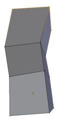
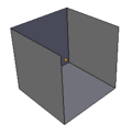
Undo all your additions, and get back to the pristine cube. Now select all four vertices of a single face. CTRL + RMB near your selection, and you should have four new vertices (corresponding to the original four you selected), plus a new face connecting them, plus
four
new faces connecting them to the original four. (You may not have noticed it, but the face formed from the original four vertices has been removed as well.) Another CTRL + RMB does the same thing again. So with just a few clicks, you started with a cube and ended up with something (see at right) that is starting to resemble — who knows? A square-cross-sectioned piece of some wonky-looking pipe, perhaps?
::取消所有加法,然后回到原始立方体. 现在选择单面的四个顶点. CTRL + RMB 在您的选择附近,您应该有四个新的顶点 (与您选择的原始四个相对应),加上一个新的面部连接它们,加上四个新的面部连接它们与原始四个. (您可能没有注意到,但由原始四个顶点形成的面也被删除了.) 另一个 CTRL + RMB 再次做同样的事情. 所以只需点击几下,您从一个立方体开始,最终得到了 (见右图) 开始类似于的东西. 谁知道? 方形截面的管子,也许?
Simplifying Things
简化的物体
It is possible to remove vertices without leaving holes behind in the mesh, by merging two or more vertices into one. Select the vertices you want to merge, and press ALT + M ; a menu will pop up with some options, including whether to position the resulting vertex in the middle of the ones being merged, or at the position of the first or last one you selected. The resulting vertex inherits all the edges that were connected to the vertices being merged, as well as the faces connected between those edges.
::通过将两个或两个以上的顶点合并为一个,可以在网格中不留下洞的情况下删除顶点.选择您想要合并的顶点,然后按ALT + M;一个菜单将弹出一些选项,包括是否将结果的顶点放置在被合并的顶点中间,或者在您选择的第一个或最后一个位置.结果的顶点继承了与被合并的顶点连接的所有边缘,以及这些边缘之间的连接面.
Sometimes an operation creates duplicate vertices in exactly the same positions, or very close together. You can merge these
en masse
by ensuring you have selected all possible candidate vertices (e.g. the whole mesh), bringing up the Vertex Specials menu ( W ) and selecting the “Remove Doubles” item. Look for a message saying “Removed
n
vertices” to show briefly in the Info window. If
n
is 0, nothing was done. If you look in the lower left part of the Tool shelf, you will see a “Remove Doubles” panel has appeared, with a “Merge Distance” slider that governs the maximum distance allowed between vertices that are merged. Change this value as appropriate (either by clicking on the left and right arrows, or by clicking and typing in a new value and pressing ENTER ), and the Remove Doubles operation is immediately redone. A new message will indicate how many vertices were removed. Simply keep adjusting the value until you are satisfied you haven't removed too many or too few vertices.
::有时操作会在完全相同的位置或非常接近的位置创建重复顶点. 通过确保选择了所有可能的候选顶点 (例如整个网格),打开顶点特点菜单 (W ) 并选择"删除重复"项,您可以将这些重复顶点集成. 寻找一条消息,说"删除 n 个顶点"在信息窗口中简要显示. 如果 n 为 0, 没有任何操作. 如果您在工具架的左下方,您会看到一个"删除重复"面板出现,有一个"合并距离"滑块,控制合并的顶点之间的最大允许距离. 根据需要更改此值 (单击右和左箭头,或键入和键入新的值并按 ENTER),然后操作"删除重复"会立即显示出一个