Blender 3D:零基础到专业级-单元2:基本建模和着色
You previously
scratched the surface
of the tools that Blender provides for editing meshes. This page will introduce more of them.
::您之前已经在Blender提供用于编辑网格的工具的表面上进行了划痕. 这页将介绍更多的工具.
Adding More Mesh Pieces
::增加更多的网格
Start with the default cube again. Select it and TAB into Edit mode. Press SHIFT + A to bring up the Add menu. Instead of all the submenus with all the objects you could add in Object mode, you will see only a single menu containing only mesh objects. Select another cube, and use G to move it away from the first cube.
::从默认立方体开始.选择它并将TAB转入编辑模式.按SHIFT+A以显示添加菜单.在Object模式中,您可以添加所有对象的子菜单,而不是所有子菜单,您只会看到一个包含网格对象的单个菜单.选择另一个立方体,并使用G将其从第一个立方体移开.
If you TAB into Object mode, you will see that the two cubes look like separate, disconnected objects, but they are in fact one object, and cannot be selected separately in Object mode. You can TAB back into Edit mode, and make connections between the vertices of the two cubes, which you cannot do with separate objects. Therefore:
::如果将TAB转换为对象模式,你会看到两个立方体看起来像是分开的,不连接的对象,但它们实际上是一个对象,在对象模式中不能单独选择.你可以重新转换为编辑模式,并在两个立方体的顶点之间进行连接,而这在单独的对象中是不可能的.因此:
|
|
A single mesh object can be made of separate, disconnected pieces.
|
Linked Selections
::相关的选择
If you have some part of a mesh selected, pressing CTRL + L will select all other parts of the mesh that are connected to the already-selected parts. In the above case of the object made up of two disconnected cubes, you can RMB on a single vertex of one cube, then use CTRL + L to select all the rest of that cube but not the other.
::如果您选择了网格的一部分,按Ctrl + L将选择连接到已经选择的部分的所有其他网格部分.在上面的两个断开的立方体组成的对象中,您可以在一个立方体的单个顶点上RMB,然后使用Ctrl + L来选择该立方体的其余部分,但不是另一个.
Another way to do linked selections is to simply move the mouse over some part of the piece you want to select, and press L to immediately select everything connected to that. Conversely, SHIFT + L will
un
select everything connected to the vertex under the mouse.
::另一个方法是将鼠标移动到你想要选择的部分,然后按L即时选择与之连接的东西.反之,SHIFT+L将取消与鼠标下方顶点连接的东西.
Separating and Joining Meshes
::分离和连接网
You can separate a part of a mesh into its own object. The part you are separating doesn’t have to be disconnected from the rest of the mesh. Simply select the part you want to separate in Edit mode, and press P , and in the menu that appears, choose “Selection”. You will see the selected part immediately change to a reddish-orange highlight, indicating it is part of the object selection but not the active object.
::您可以将网格的一部分分离为自己的对象.您将分离的部分不必与网格的其余部分断开连接.只需在编辑模式中选择您想要分离的部分,然后按P,并在显示的菜单中选择"选择".您将看到所选部分立即变为红色的突出显示,表明它是对象选择的一部分,但不是活动对象.
Conversely, you can join two or more mesh objects into one. Select all the desired objects in Object mode, and press CTRL + J , and you will see them all immediately take on the orange-yellow highlight indicating they are
all
the active object. TAB into Edit mode, and you can confirm all are editable as part of the same mesh object.
::另一方面,您可以将两个或多个网格对象合并为一个.在对象模式中选择所有所需的对象,然后按Ctrl+J,您将看到它们都立即亮出黄色的突出显示,表明它们都是活跃的对象.将TAB转换为编辑模式,您可以确认所有都可以作为同一网格对象的一部分进行编辑.
Proper Extrusion
::适当的挤出
You previously discovered how to add whole new sections to a mesh with CTRL + LMB . Blender also has a proper Extrude function, which lets you do this with a bit more control.
::混合器还有一个适当的挤出功能, 这让你有更多的控制.
Start with the default cube, as usual. Go into Edit mode. Select just the top four vertices. Press E to start extruding, and move the mouse roughly along the direction of the Z-axis. You will find yourself dragging out a whole new face formed from four new vertices connected to the ones you previously selected. You will notice also that the movement of the newly-added part of the mesh is automatically constrained to be parallel to the Z-axis. Press LMB or ENTER to finish the extrusion operation.
::开始使用默认的立方体,如常.进入编辑模式.只选择前四个顶点.按E开始挤出,并将鼠标大致沿着Z轴的方向移动.您将发现自己拖出一个由四个新的顶点组成的全新的面,连接到您之前选择的顶点.您还会注意到,网格的新添加部分的运动自动被限制为平行于Z轴.按LMB或ENTER完成挤出操作.
Deselect everything. Now try selecting another four vertices of the original cube, say making up a face pointing along the X-axis. Now if you extrude these, you will see that the extrusion is automatically constrained to move only parallel to the X-axis.
::取消所有选项. 现在尝试选择原立方体的另外四个顶点, 举例说, 构成一个沿着X轴指向的面. 现在如果你挤出这些, 你会看到挤出自动被限制只与X轴平行移动.
A quirk of the extrusion function is that if you press E and then immediately abort with RMB or ESC ,
the additional mesh piece is still created
, but it is left in the same position as the original mesh. To
really
abort the extrusion, you have to undo it with CTRL + Z .
::挤出函数的一个特点是,如果按下E,然后立即用RMB或ESC中止,则仍然会创建额外的网格片,但它会留在与原始网格相同的位置.为了真正地中止挤出,你必须用CTRL+Z来撤消它.
More Extrusion Options
::更多的挤出选项
ALT + E brings up the Extrude menu, which gives you access to more options, depending on what you have selected:
::根据您所选的选项, 您可以访问更多选项:
-
“Region”—extrude the entire selected area as one, exactly equivalent to E .
::区域将整个选定的区域作为一个完全等同于E的区域. -
“Individual Faces”—if you have more than one face selected, then they are extruded separately. In particular, any edge common to two selected faces will give rise to two separate extruded edges, rather than one.
::个别面如果您选择了多个面,则它们将分别挤出.特别是,两个选定的面的任何边缘都会产生两个单独的挤出边缘,而不是一个. -
“Edges Only”—extrudes only the edges; new faces are created only connecting the new edges to the existing ones, not between the new edges.
::Edges Only只出边缘;新面只能通过将新边缘连接到现有边缘而不是在新边缘之间创建. -
“Vertices Only”—extrudes only the vertices; edges are created only connecting the new vertices to the existing ones, not between the new vertices, and no new faces are created.
::只有顶点只能挤出顶点;边缘只能连接新顶点与现有顶点,而不是在新顶点之间,并且不会创建新的面.
Edge Loop Selection
::边缘循环选择
Edge loops
are an important concept when constructing meshes. They are so important that Blender provides a shortcut for selecting an entire edge loop with one click: ALT + RMB on an edge or vertex that is part of the loop you want to select, and it will select the entire loop. Alternatively, ALT + SHIFT + RMB adds an edge loop to the selection; or, if the part you click on is already selected, it will
deselect
the entire loop.
::边缘循环是构建网格时的一个重要概念.它们非常重要,Blender提供了一个快捷方式,可以用一键选择整个边缘循环:ALT + RMB在边缘或顶点上,这是你想要选择的循环的一部分,它将选择整个循环. 另一个选择,ALT + SHIFT + RMB将添加边缘循环到选择中;或者,如果您点击的部分已经被选择,它将取消选择整个循环.
For example, try experimenting with a UV sphere: every line of “latitude” and “longitude” in this mesh is an edge loop.
::例如,试试使用紫外线球体:这个网格中的每一条度和经线都是边缘环.
Loop Cuts
::环切割
Sometimes you need to add more vertices to the interior part of a mesh, perhaps to flesh in some detail. The loop cut function lets you add more edge loops between existing ones.
::有时需要在网格的内部部分添加更多的顶点,也许是为了细节化.循环切割功能允许你在现有的边缘之间添加更多的边缘循环.
Ensure you are in Edit mode. It doesn’t matter what parts of the mesh are currently selected. Press CTRL + R to activate the Loop Cut function. You will see a magenta-coloured loop wrap itself around different parts of the mesh as you move the mouse. You can press RMB or ESC to abandon the operation at this point, or once you see the loop appearing around the correct part of the mesh, you can use LMB or ENTER to proceed. Now the magenta colour changes to the usual orange-yellow selection highlight, and will now restrict itself to sliding along this section of the mesh as you move the mouse. If you press LMB or ENTER at this point, you will end up with a new loop of vertices and edges at the last-shown point, while RMB or ESC will still create the new loop, but leave it positioned at the midpoint.
::确保您处于编辑模式. 现在网格的哪些部分是当前选择的. 按Ctrl+R激活循环切割功能. 当您移动鼠标时,您将看到一个红色的循环环绕网格的不同部分. 您可以按RMB或ESC放弃操作,或者一旦您看到网格正确部分周围出现的循环,您可以使用LMB或ENTER继续. 现在红色将变为通常的黄色选择突出点,并且当您移动鼠标时将限制自己沿着网格的这一部分滑动. 如果您在此时按LMB或ENTER,您将在最后显示的点上获得一个新的顶点和边缘循环,而RMB或ESC仍将创建新的循环,但将其放置在中间点.
When the loop is still at the magenta stage, you can use the mouse wheel to increase the number of cuts to 2 or more. You can also type a number of cuts using 0KEY ... 9KEY .
::当循环还处于红色阶段时,您可以使用鼠标轮增加切割数量到2个或更多.您也可以使用0KEY ... 9KEY输入一些切割.
Edge Loop Deletion
::删除边缘循环
Conversely, you can get rid of edge loops as well, reducing the complexity of the surface without leaving holes in it. Select the edge loop (the quick way is ALT + RMB on a component edge or vertex as described above), then bring up the deletion menu ( DEL or X ) and select “Edge Loop”. The selected loop will disappear, and adjacent edges and faces will be merged.
::另一方面,您也可以消除边缘循环,减少表面的复杂性,而不会留下洞.选择边缘循环 (快速方法是按ALT+RMB在组件边缘或顶点上),然后打开删除菜单 (DEL或X) 并选择"边缘循环".选定的循环将消失,并将相邻的边缘和面部合并.
Subdividing Parts
::部分的分类
A loop cut always cuts a complete loop. Alternatively, you can subdivide just a selected part of the mesh: make your selection, then press W to bring up the Vertex Specials menu, and select the top option, “Subdivide”. This will create one cut, but a panel will appear at the lower left of the Toolshelf ( T to make it visible at the left of the 3D view if it’s not), where you can alter the number of cuts and other settings. This same option is also available on Edge Specials CTRL + E .
::循环切割总是切割一个完整的循环. 另外,您可以只划分网格的选定的部分:进行选择,然后按W以显示顶部特种菜单,并选择顶部选项"分区". 这将创建一个切割,但在工具架的左下方会出现一个面板 (T使其在3D视图的左侧可见),您可以更改切割数量和其他设置. 这种相同的选项也可在边缘特种 CTRL + E 上使用.
Another option is the second one on the W menu: “Subdivide Smooth”. This one computes a
Catmull-Clark
interpolation to give more of a curve rather than a flat subdivision.
::另一个选项是W菜单上的第二个选项:Subdivide Smooth. 这种选项计算了Catmull-Clark插值,以提供更多的曲线而不是平面分区.
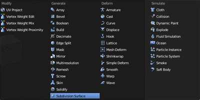
Subdivision Surface Modifier
::区块表面修改器
A modifier causes some change to the geometry of an object just before it gets rendered. The change does not affect the object as you view and edit it in the 3D view, or as it is stored in the document (unless you apply the modifier, which makes the change permanent). This allows you to create some complicated effects at render time, while the original mesh stays simple and easy to edit. Modifiers for the active object are applied and controlled in the Modifiers
![]() tab in the Properties window.
tab in the Properties window.
::修改器在染之前会对对象的几何变化产生一些影响. 修改器不会影响您在3D视图中查看和编辑对象,或者它存储在文档中 (除非您应用修改器,从而使变更永久). 这允许您在染时创建一些复杂的效果,而原始网格保持简单易于编辑. 适用于活动对象的修改器在属性窗口的修改器选项卡中应用和控制.
A subdivision surface modifier (also known as a “subsurf” modifier) applies the Catmull-Clark interpolation discussed above as a modifier. Being a modifier, it applies to the entire object, not just to selected vertices. But since the original mesh is preserved, you use it as a
control cage
to adjust the shape of the interpolated curve.
::划分表面修饰器 (也称为subsurf修饰器) 应用了上面讨论的卡特穆尔-克拉克插值作为修饰器.作为修饰器,它适用于整个对象,而不仅仅是选择的顶点.但是由于保留了原始网格,您可以将其用作控制来调整插入曲线的形状.
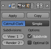
Start with the default cube selected in Object mode, as usual. Go to the Modifiers tab in Properties
![]() . When you select “Subdivision Surface” from the “Add Modifier” menu, a new panel appears as at right. Notice the two value sliders under the “Subdivisions” heading; 'View' controls the level of subdivision within the 3D view, while 'Render' applies to the actual render; the higher the number of levels, the closer to a curve the interpolated geometry becomes. Having two separate settings for working environment and render allows for faster operation in the 3D view, with the usual tradeoff of lower quality, while still allowing maximum quality for the final render.
. When you select “Subdivision Surface” from the “Add Modifier” menu, a new panel appears as at right. Notice the two value sliders under the “Subdivisions” heading; 'View' controls the level of subdivision within the 3D view, while 'Render' applies to the actual render; the higher the number of levels, the closer to a curve the interpolated geometry becomes. Having two separate settings for working environment and render allows for faster operation in the 3D view, with the usual tradeoff of lower quality, while still allowing maximum quality for the final render.
::开始在Object模式中选择的默认立方体,如常.进入属性中的修改器选项卡.当您从"添加修改器"菜单中选择"分区表面"时,右边会出现一个新面板.请注意"分区"标题下的两个值滑块;"视图"控制3D视图中的分区级别,而"染"适用于实际染;层次数越多,插曲几何就越接近曲线.在3D视图中设置两个独立的工作环境和染环境,可以更快地操作,但通常的质量较低,同时仍然允许最终染的质量达到最高.
|
|
Keyboard shortcuts:
Because the Subdivision Surface modifier is so heavily used, there is a set of hotkeys for adding the modifier to the current object if it doesn’t already have one, and setting the number of subdivision levels in the 3D view: CTRL + 1KEY .. CTRL + 5KEY for setting the view levels to 1 .. 5 respectively.
|
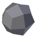
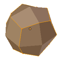
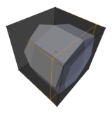
As soon as you add the modifier, the appearance of the cube should change to look something like at right (here shown with just one level of subdivision).
::立方体的外观应该会像右边一样变化 (这里只显示一个分层).
The upper part of the panel (from the “Apply” and “Copy” buttons upwards) is common to all modifiers. Note the X button at the right. Clicking it gets rid of the modifier. Notice also a group of 4 icon buttons in the middle, the leftmost two look like a camera and an eye. The icons are defined as follows (from left to right):
::面板的上部分 (从"应用"和"复制"按向上) 是所有修改器的共同部分.请注意右边的X按.点击它可以消除修改器.还请注意中间的一组4个图标按,最左边的两个看起来像摄像机和眼睛.图标的定义如下 (从左到右):
-
Use the modifier during rendering
::在染过程中使用修改器 -
Show the modifier effect in the 3D view
::在3D视图中显示修改器效果 -
Show the modifier effect in the 3D view in Edit mode (if this is unchecked and the previous one is checked, the modifier effect disappears while in Edit mode)
::在编辑模式下显示3D视图中的修改效果 (如果未选中此选项,并且选中前一个选项,则在编辑模式下修改效果会消失) -
Show the mesh as though the modifier were applied to it in Edit mode.
::显示网格, 仿佛修改器是在编辑模式下应用的.
Unchecking the first one lets you disable the modifier without losing its settings. The remaining three can be handy if you’re trying to disentangle the effects of different modifiers during editing.
::如果您在编辑过程中想解开不同修改器的影响,则其他三种方法可能很方便.
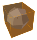
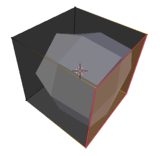
When the third button is enabled, the mesh will look like this in Edit mode. The original mesh remains highlightable and editable. A preview of the effect of the modifier is also visible, and responds immediately to any changes made to the original mesh. (Try moving some vertices around, and see what happens.)
::当第三个按启用时,网格在编辑模式下会看起来像这样.原始网格仍然可以突出显示和编辑.修改器效果的预览也可见,并立即响应对原始网格进行的任何更改. (尝试移动一些顶点,看看会发生什么.)
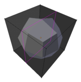
The fourth button goes one step further and acts as if the modifier has already been applied, while allowing you to edit only those parts corresponding to the original mesh. (This button affects the behavior of the third button. It cannot be used independently, and may disappear if the third button is unchecked.)
::第四个按更进一步,它像已经应用了修改器一样,同时只允许你编辑与原始网格相对应的部分. (这个按影响第三个按的行为.它不能独立使用,如果第三个按未被选中,它可能会消失.)
Sharpening the Curves
::提高曲线的敏度
The subdivision surface modifier offers much more control over the resulting shape than might be apparent from above. For example, you may not want uniform curvature everywhere, you may want some parts of the shape to have sharper edges. This can be achieved in two ways:
::分区表面修饰器提供了比从上面看来更大的控制结果的形状.例如,你可能不希望在所有地方均曲线,你可能希望形状的某些部分有更利的边缘.这可以通过两种方式实现:
-
by applying a
crease
value to selected edges
::通过对选定的边缘应用纹值 -
by strategic positioning of additional vertices in the control-cage mesh.
::通过在控制网上战略定位额外的顶点.
Applying a Crease
::应用一个
Select the edges where you want the curve to be sharper. Press SHIFT + E . Note how the curve gets pulled more or less closer to those edges as you move the mouse. The selected edges take on a magenta colour, indicating they have a nonzero crease value applied.
::选择你希望曲线更利的边缘.按 SHIFT + E . 注意鼠标移动时曲线如何被拉近到这些边缘. 选择的边缘会变成色,表明它们应用了非零值.
The crease value can be seen and edited in the Transform panel at the top of the Properties Shelf at the side of the 3D view (you can toggle its visibility with N . Values can range from 0.0 (no crease, the default) to 1.0 (maximum sharpness of the edge).
::纹值可以在3D视图侧面的属性架顶部的转换面板中查看和编辑 (您可以使用N来切换其可见性. 值可以从0.0 (没有纹,默认值) 到1.0 (边缘最大度) 之间.
Adding Vertices
::增加顶点
For example, start with the subdivided cube example as above. Press CTRL + R to start a loop cut, and position the magenta outline something like this:
::例如,从上面的分立方体示例开始.按Ctrl+R开始循环切割,并将红色轮定位为这样:
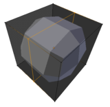
Press LMB or ENTER ...
::按下 LMB 或 ENTER ...
... and move the mouse so the newly-added loop moves closer to one side of the cube. See how the subdivided mesh develops a sharper curve on this side?
::看到分成网格如何在这个侧面发展出更的曲线?
To confirm the placement of the new loop, press LMB or ENTER .
::要确认新循环的位置,请按 LMB 或 ENTER .
Which to Use?
::哪一个?
The basic principle is, the closer together the vertices are, the more control you have over the curve at that point. So the question is, do you just want a sharper edge, or do you want more detail? That will govern whether you need to add vertices, or just apply a crease to the existing edges.
::基本原理是,顶点越靠近,你就越能控制曲线的位置. 问题是,你只想一个更尖的边缘,还是你想要更多的细节? 这将决定你是否需要添加顶点,或者只是在现有边缘上应用.