Blender 3D:零基础到专业级-单元2:基本建模和着色
Bézier Curves
::贝齐尔曲线
-
First start a new Blender project, and delete the default cube.
::首先开始一个新的Blender项目, 并删除默认的立方体. -
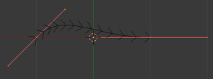
Press: SHIFT + A → Curve → Bezier to create a new curve. Switch to top view NUM7 for a clearer look. You may want to zoom in a bit as well. TAB into Edit mode.
::按:SHIFT + A → 曲线 → Bezier创建一个新的曲线. 切换到顶部视图NUM7以获得更清晰的视图. 您也可能想要缩小一点. 按键进入编辑模式.
The black line with the extra angled lines like centipede legs coming off it is the Bézier curve. The white or orange dots are the
control points
, with the ones in the middles of the pink handle lines defining the endpoints of the curve segment.
::黑线与额外的角线像百脚脚脱落是贝齐尔曲线.白色或色点是控制点,粉红色手柄线中间的点定义了曲线段的末点.
Press A to deselect the selection, so that all the control points turn black, and the lines connecting them turn red. You can RMB on any point to select it; however, selecting a curve endpoint selects the entire handle line passing through it.
::按A取消选择,使所有控制点变黑,连接它们的线变红.您可以在任何点上选择它;然而,选择一个曲线末点选择整个经过它的控制线.
You can move a selected point in the usual way, with G : note how moving an endpoint causes the curve to bend so it always connects to the endpoint. Moving just a point at the end of a control handle affects the inner part of the curve, making it bend more or less sharply away from the endpoint: try moving one of these points around, and note how the handle gets longer or shorter, and automatically rotates as necessary to remain a single straight line.
::你可以以通常的方式移动选定的点,用G:注意移动一个端点会使曲线曲,因此它总是连接到端点.移动控制手柄的末端的点会影响曲线的内部部分,使它从端点上曲得多或少:尝试移动其中一个点,并注意手柄如何变长或变短,并根据需要自动旋转以保持单一的直线.
Alternatively, you can select an endpoint (which selects the entire control handle, remember) and use R to rotate the handle, and S to make it longer or shorter.
::选择一个终点 (选择整个控制手柄,请记住) 并使用R旋转手柄,
Resolution
::分辨率
In the Curve Context
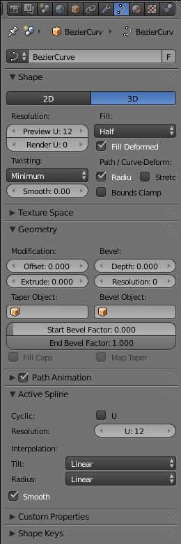
![]() in the Properties window, further down you will see the Active Spline panel. (This is only visible in Edit mode.) Note the editable field next to the label “Resolution:”, probably showing “U: 12”. That number governs the number of straight-line segments that the curve is converted into for rendering purposes; the more of these, the smoother the result, but it will add a bit to the render time.
in the Properties window, further down you will see the Active Spline panel. (This is only visible in Edit mode.) Note the editable field next to the label “Resolution:”, probably showing “U: 12”. That number governs the number of straight-line segments that the curve is converted into for rendering purposes; the more of these, the smoother the result, but it will add a bit to the render time.
::在属性窗口的曲线上下方,您将看到主动分线面板. (仅在编辑模式中可见.) 注意标签旁边的可编辑字段 解析度:,可能显示 U: 12.该数字控制了曲线转换为染目的的直线段数量;这些越多,结果就越顺,但它会增加染时间.
|
|
That’s right. As embarrassing as it may sound, Blender cannot actually render curves.
It has to approximate each curve by a series of straight-line segments before rendering.
|
This resolution setting is also used when converting the curve to a mesh ( ALT + C ).
::这种分辨率设置也用于将曲线转换为网格 (ALT + C).
Extending Your Curve
::延长你的曲线
So far your Bézier curve only has one segment. You can add segments in several different ways:
::现在,贝济尔曲线只有一个段. 你可以用几种不同的方式来增加段:
-
Back in EDIT mode, RMB on an endpoint at either end of the whole curve, and use E to extend a new curve segment connected to the same endpoint. (We won’t say “extrude”, to avoid confusion with a different extrusion function discussed further down.)
::在EDIT模式中,在整个曲线的两端的端点上使用人民币,并使用E来扩展与同一端点连接的新曲线段. (我们不会说"挤出",以避免与下面讨论的不同挤出函数混). -
RMB on an endpoint at either end of the whole curve, and CTRL + LMB where the endpoint of the new segment will go; the new segment will immediately be added between the previous endpoint and the new one.
::在整个曲线的两端的终点上,人民币, CTRL + LMB,新段的终点将进入;新段将立即在前一个终点和新段之间添加. -
Select the endpoints of a single curve segment, press W and choose “Subdivide” from the menu. This splits the curve segment into two new connected segments.
::选择单个曲线段的终点,按W,从菜单中选择"分成". 这将曲线段分割成两个新的连接段.
Note that if you CTRL + LMB when the selection is not precisely one endpoint of the whole curve, it will add a new handle that is not connected to any part of the existing curve. You can extend from this handle to create a whole set of new curve segments that are still part of the same curve object, even though there are no lines running between this piece of curve and the previous one. You can join two separate pieces of the curve with a new segment by selecting an endpoint of each and pressing F .
::注意,如果在选择不是整个曲线的某个终点时,Ctrl + LMB 将添加一个与现有曲线的任何部分无关的新手柄.您可以从这个手柄扩展,创建一整组新的曲线段,这些段仍然是相同曲线对象的一部分,即使在这个曲线段和前一个曲线之间没有线条.您可以通过选择每个曲线的终点并按F连接曲线的两个单独的段.
You can also add new pieces with SHIFT + A in Edit mode.
::在编辑模式下,您还可以使用SHIFT+A添加新作品.
|
|
Curves cannot have branches.
However, depending on your purposes, you could simulate the appearance of a branch by overlapping the end of one piece on top of another one.
|
Removing Points and Segments
::删除点和段
You can delete any control points by selecting them and using the familiar DEL or X . The menu that pops up asks you if you want to remove the “Selected” points, the “Segment”, or “All”.
::您可以通过选择它们并使用熟悉的 DEL 或 X 来删除任何控制点.弹出的菜单会询问您是否想删除"选择"点",段落"或"全部"点.
-
“Selected” removes all points that are part of the same handle(s) as the selected point(s). Removing an endpoint of a curve piece removes the connected segment. Removing an interior endpoint causes the replacement of the curve segments on either side of it with a new one running directly between their remaining endpoints. Thus, the curve piece of which that segment was a part remains a single curve piece afterwards.
::Selected删除了与所选点相同的头 (s) 组成的所有点.删除曲线片的末端将删除连接的段.删除内部末端将导致两侧的曲线段被一个直接在其剩余末端之间运行的新片所取代.因此,该段是其中的一部分的曲线片之后仍然是一个单一的曲线片. -
“Segment” removes a segment between two connected endpoints. If neither endpoint was an endpoint of the curve piece, then the remainder of that piece of the curve becomes two disconnected pieces.
::段取消两个连接的末端点之间的段.如果没有一个末端是曲线片的末端点,则曲线片的剩余部分成为两个断开的片. -
“All” removes
all
of the control points, leaving an empty curve object!
::All删除了所有的控制点,留下一个空的曲线对象!
Handle Types
::处理类型
So far, all the handles on your curve have been
aligned
. This means that adjacent curve segments are guaranteed to join smoothly. If you select a control point and press V , you will get a menu allowing you to set other types for the handle:
::到目前为止,您的曲线上的所有手柄都已对齐. 这意味着相邻的曲线段有保证顺利连接. 如果您选择控制点并按V,您将获得一个菜单,允许您设置其他类型的手柄:
-
Free
means the two parts of the handle on either side of the endpoint are free to rotate independently, so the two curve segments can now meet at a corner.
::自由意味着端点两侧的两个部分可以自由自主旋转,因此两个曲线段现在可以在角落相遇. -
Vector
means the selected part of the handle points at the other endpoint of the same curve segment, and will keep pointing that way even if you move either endpoint. If you set the part of the handle from the other endpoint pointing back this way to “Vector” as well, then the curve segment becomes a straight line. However, as soon as you explicitly move the handle itself, it reverts to being “free”.
::矢量指的是选择的柄部分,指向同一曲线段的另一端点,即使移动任何一个端点,它也会继续指向那个端点.如果您将柄部分从另一端点指向回的方向设置为矢量,则曲线段将成为直线.然而,一旦您明确移动柄本身,它就会恢复为自由. -
Automatic
is like “aligned”, except Blender will automatically adjust the orientation of the handles as you move the endpoints, to try to keep the curve smooth. Moving either end of the handle will change it back to “aligned” type.
::自动是像"对齐"的,除了Blender会自动调整手柄的方向,当你移动端点时,试图保持曲线平滑.移动手柄的任何一端将会将其更改为"对齐"类型.
2D Versus 3D
::两维与三维
At the top of the Shape panel in the Curve Context
![]() in the Properties window, you will see buttons labelled “2D” and “3D”. “2D” means the points of the curve are constrained to lie in a single plane, while “3D” means they are free to be located anywhere in 3D space relative to each other. Initially “3D” should be selected.
in the Properties window, you will see buttons labelled “2D” and “3D”. “2D” means the points of the curve are constrained to lie in a single plane, while “3D” means they are free to be located anywhere in 3D space relative to each other. Initially “3D” should be selected.
::在属性窗口的曲线上下文中,在"形状"面板的顶部,您将看到标记为 2D 和 3D 的按. 2D 表示曲线的点被限制在单一平面内,而 3D 表示它们可以在3D空间中的任何位置相对彼此自由. 首先,应选择 3D.
Try moving one point along the Z axis. Now click the “2D” button, and you should see all the points you moved snap back into the same plane as the rest. Also the “centipede legs” along the curve should have disappeared (their presence indicates a 3D curve). You can alter the orientation of this plane by TAB bing into Object mode and then rotating R the whole curve about any desired axis.
::试着沿 Z 轴移动一个点. 现在点击 2D 按,你应该看到所有移动的点都会与其他点重新进入同一平面. 沿曲线的 百足也应该消失了 (它们的存在表明了 3D 曲线). 你可以通过 TAB 入 Object 模式,然后旋转 R 绕任何所需的轴旋转整个曲线来改变这个平面的方向.
Closing, Filling and Extruding
::封闭,填充和挤压
Each curve piece can be individually
closed
, meaning that an extra curve segment is automatically added between the two endpoints of the piece. This is governed by the “Cyclic: U” checkbox in the Active Spline panel in the Curve Context
![]() . Each closed piece of a 2D curve is automatically filled to form a flat surface.
. Each closed piece of a 2D curve is automatically filled to form a flat surface.
::每个曲线片可以单独关闭,这意味着在片的两个末端之间自动添加一个额外的曲线段.这是由曲线上下文中的Active Spline面板中的周期:U选框所规定的. 2D曲线的每个关闭片自动填充以形成平面.
|
|
What happens if two filled pieces of a 2D curve cross?
If you try this, you will see that the overlapping parts are
subtracted
from the filled areas, leaving holes. Those familiar with the various options for filling Bézier curves in 2D drawing programs will recognize this as the
even-odd fill rule
.
|
The curve can also be
extruded
into the third dimension, effectively turning it into a ribbon-like shape. Look for the “Extrude:” editable field in the Geometry panel, and put a nonzero value into that to specify the extrude width.
::曲线也可以挤出到第三维,有效地将其转化为带状的形状. 在几何面板中寻找"挤出:"可编辑字段,并将非零值放在其中以指定挤出宽度.
If you extrude a 2D closed curve, the flat surface becomes a solid object, and the result is a
prism
—a solid shape with a uniform, but arbitrarily complicated, cross-section.
::如果挤出一个2D封闭曲线, 平面变成一个固体物体, 结果是镜 - - 一个固体形状,
Scaling and Tilting
::缩放和倾斜
Turn your curve into a ribbon by specifying a nonzero Extrude value. Change your view so it is not exactly from the top or bottom, but at some angle. Notice how the ribbon is of constant width and always perpendicular to the plane of your curve.
::通过指定非零的外加值,将曲线转化为带.改变视图,使其不是从上或下,而是以某种角度.请注意带的宽度是恒定的,并且始终垂直于曲线的平面.
Select an endpoint, and press ALT + S . As you move the mouse, you are changing the
radius
of the endpoint from its default 1.0 value, and this causes a corresponding scale factor to be applied to the width of the ribbon at that point. You can see (and also edit) this radius value in the Properties Shelf N , in the Transform panel at the top.
::选择一个终点,然后按ALT+S. 当你移动鼠标时,你正在改变终点的半径从默认的1.0值,这导致相应的缩放因子应用于该点的带宽. 你可以在属性架N中看到 (也可以编辑) 这个半径值,在顶部的转换面板中.
With an endpoint selected, now try CTRL + T (
Note:
This only has an effect with 3D curves, not 2D ones). Now as you move the mouse, you are applying a
tilt angle
, which correspondingly alters the angle of the ribbon at that point. This value is also accessible in the Transform panel in the Properties Shelf.
::选择了一个端点,现在尝试 CTRL + T (注意:这只对 3D 曲线有影响,而不是 2D 曲线). 当你移动鼠标时,你正在应用一个倾斜角度,这对应地改变了该点上的带的角度. 这个值也可以在属性架中的转换面板中访问.
The scale radius and tilt become particularly useful when you apply a
bevel shape
to the curve—then you will start to get much more complicated shapes than simple ribbons.
::尺度半径和倾斜变得特别有用, 当你应用一个形曲线那么你将开始得到比简单的带更复杂的形状.
NURBS Curves
::其他
Start a new Blender document, and get rid of the default cube.
::开始一个新的混合器文件, 并摆脱默认的立方体.
This time, do SHIFT + A → Curve → Nurbs Curve, and TAB into Edit mode. The result looks a bit similar to a Bézier, except there are no control handles, only the segment endpoints. Instead of dragging handles, you can adjust a weighting assigned to each control point. Bring up the Properties Shelf with N if it is not already visible. If you have a single point selected, in the Transform panel at the top, you should see four editable fields under the heading “Control Point:”, labelled “X:”, “Y:”, “Z:”, and “W:”. The first three are of course the position of the point; the “W” value is like a gravitational field strength that attracts the curve to the point. Try adjusting this, and see how it influences the shape of the curve near that point.
::这一次,做SHIFT + A → 曲线 → 曲线,并将TAB转换为编辑模式.结果看起来有点像Bézier,除了没有控制手柄,只有段末端.而不是拖动手柄,你可以调整分配给每个控制点的权重.如果还没有可见,请用N来显示属性架.如果您选择了一个点,在顶部的转换面板中,您应该在标题下看到四个可编辑的字段: 控制点:,标记为 X:, Y:, Z:和 W:.前三个是点的位置; W值就像一个引力场,吸引曲线到点.尝试调整这一点,看看它如何影响该点附近的曲线形状.
|
|
Ignore the “Weight:” field further down.
That has a different purpose we won’t discuss here.
|
You can move endpoints in the usual way, but there are no handles to rotate. All the other options for add and deleting endpoints apply as for Bézier curves: CTRL + LMB or E xtend, W →Subdivide, DEL eting Select/Segment/All. The curve can be 2D/3D, extruded and cyclic, and each endpoint has a ALT + S cale radius and a CTRL + T ilt angle. In the “Active Spline” panel in Object Properties, there is an additional “Endpoint: U” checkbox which forces the curve to pass through the endpoints (this is ignored if Cyclic is enabled).
::您可以以通常的方式移动端点,但没有旋转的手柄.所有其他添加和删除端点的选项都适用于贝齐尔曲线:CTRL + LMB或E xtend,W →Subdivide,DEL eting Select/Segment/All.曲线可以是2D/3D,挤出和循环,每个端点都有ALT + S cale半径和CTRL + T ilt角度.在对象属性中的"主动分线"面板中,有一个额外的"端点:U"选框,强迫曲线通过端点 (如果启用循环,则会忽略此选项).

|
You can mix Bézier and NURBS curve pieces in the same curve object. Just use SHIFT + A to start a new piece of the desired type in Edit mode.
|
SHIFT + A →Curve→Nurbs Circle inserts a NURBS curve with eight control points arranged in a square, “Cyclic: U” enabled, and the weights of the corner points adjusted so the curve is an exact circle.
::SHIFT + A →Curve→Nurbs Circle插入一个NURBS曲线,其中有八个控制点排列成一个正方形,启用循环:U,并且对角点的权重进行调整,使曲线成为一个精确的圆圈.
SHIFT + A →Curve→Path inserts a NURBS curve with five control points in a straight line, and the “Endpoint: U” option already checked.
::SHIFT + A →Curve→Path 插入一个 NURBS 曲线,其中五个控制点在直线上,并且已经选中了 Endpoint: U 选项.
Which Curves To Use?
::如何选择?
As mentioned earlier, NURBS curves are heavily used in CAD applications, while Béziers are popular in 2D drawing applications. If you are importing data from these applications, then you won’t have any choice about which one you end up with.
::如前面提到的,NURBS曲线在CAD应用中被广泛使用,而Béziers则在2D绘图应用中很受欢迎.如果您从这些应用中导入数据,那么您将无法选择最终使用哪一个.
But if you are creating your own curves, then you have a choice. If you have done drawing with Bézier curves a lot, then you should feel at home with them. If you just want simple curves to deform a shape or guide an animation, NURBS curves could very well do the trick—you could even leave the W values at the default, and just add, delete and position points to get a suitable curve.
::图形的设计是非常简单的,但是如果你正在创建自己的曲线,那么你有选择.如果你经常使用贝齐尔曲线绘制图案,那么你应该对它们感到很自在.如果你只是想要简单的曲线来变形形状或引导动画,那么NURBS曲线很可能会做出这个技巧 - 你甚至可以把W值留在默认值,只需添加,删除和定位点才能得到合适的曲线.
Extruding from 2D to 3D
::从二维到三维的挤出
You may have noticed you can only modify the curve in two dimensions, and now it's time to explore the third dimension! Extruding is where you define a two dimensional 'profile' shape, and it is 'swept' through space to create a volume.
::现在是时候探索第三个维度了! 挤出是定义一个二维的"形状"形状的地方, 它是通过空间"扫描"以创建一个体积.
Noob note
Bézier circles are not true circles, they are approximations. For artistic purposes, this may not really matter, but for precision modelling only NURBS circles should be used. This is due to the math used to describe the Bézier and NURBS curves.
::贝齐尔圆不是真正的圆,它们是近似. 对于艺术目的,这可能并不重要,但对于精确的建模,只应该使用NURBS圆. 这是由于用于描述贝齐尔和NURBS曲线的数学.
Make a Simple Face of Bézier Curves
::简单地构建一个贝济埃曲线的面
-
Make a curve and fill it
: Being sure you are in 2D mode, Use the steps above to create something simple, and fill it in using
::确定您处于二维模式, 使用上述步骤创建简单的东西, 并使用
ALT + C .
::另一个C.
Noob note:
you may find it easier to use Bézier circles, instead of filling discrete curves.
::您可能会发现使用贝齐尔圆更容易, 而不是填充离散曲线.
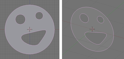
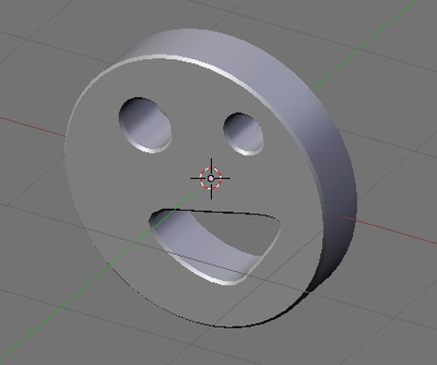
Note that the eyes and mouth of the face above are parts of the same curve object. Blender can only identify holes in a filled curve if the holes are part of the same object as the outer curve. If you had created four separate curves then filling the outer curve would have covered the eyes and mouth. To create a detached section of a curve, be in edit mode and deselect all the points ( A ). Then create new points (you will need two or three) with CTRL + LMB . Alternatively you can create the pieces as separate curve objects and join them later with CTRL + J in object mode. You might prefer the alternative way if you don't want a lot of control handles and "centipede legs" to distract you.
::注意,上面面部的眼睛和嘴是同一曲线对象的一部分.如果您创建了四个单独的曲线,则填充外部曲线将覆盖眼睛和嘴. 要创建曲线的独立部分,请处于编辑模式并取消选择所有点 (A). 然后使用CTRL + LMB创建新点 (您需要两个或三个). 或者,您可以将单独的部分创建为曲线对象,然后用CTRL + J在对象模式中将其连接起来.如果您不想让很多控制手柄和"百脚"分散您的注意力,您可能更喜欢另一种方式.
Extrude the Simple Face
::让人看得更简单

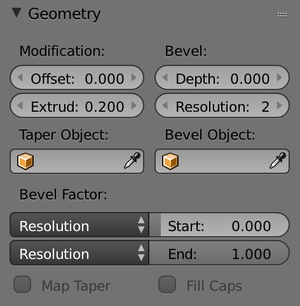
Set the extrude depth
: Click on the Object Data button and find the Geometry panel. (Older versions: find the 'Curve and Surface' box in the Editing tab of the Buttons window.) There is a slider called Extrude. Set the Extrude depth to something other than 0, and probably less than 1.
::设置挤出深度:点击对象数据按,找到几何面板. (旧版本:在按窗口的编辑选项卡中找到"曲线和表面"框.有一个叫做挤出的滑块.将挤出深度设置为 0 以外的东西,可能小于 1.
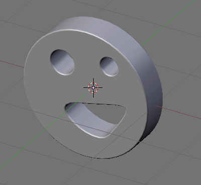
Behold, your 2d curve has transformed into a neat 3d structure. The great thing is, you can still edit the curve as if it were just 2d, and the changes will update in real time.
::您的二维曲线已经变成了一个整洁的三维结构. 很棒的是,您仍然可以编辑曲线,
Bevel the Simple Face
::让一个简单的脸
Now you have an extruded shape, you should start playing around with some of the other curve settings on offer, so here is a description of how the Bevel depth and Bevel resolution sliders work.
::现在你已经有了挤出形状, 你应该开始玩一些其他曲线设置提供, 这里是如何深和分辨率滑块的工作描述.
Try setting the Bevel depth to a small value, say 0.02. This will cut off all of the sharp edges, and give a bevelled effect all around the shape.
::设置一个小值,比如0.02 这将切断所有尖端,并给整个形状带来一个形效果.
As you may guess, Bevel resolution decides how many times the algorithm divides up an edge. Higher values than 0 result in smooth curves rather than sharp edges, but dramatically increase the number of vertices in the shape.
::像你猜想的那样,贝维尔分辨率决定算法将边缘分成多少个.高于0的值会导致光滑的曲线而不是利的边缘,但会大大增加形状的顶点数量.
Try setting the resolution to 3 or 4, you should see an effect like this:
::设置分辨率为3或4, 应该看到这样的效果: