Blender 3D:零基础到专业级-单元2:基本建模和着色
A simple, non-extruded curved line on its own will not be visible when rendered in Blender. Things are different, however, when you
bevel
the curve—that is, use some two-dimensional shape as a cross-section, and the line curve becomes a guide for extruding the shape into the third dimension.
::一个简单的,非挤出的曲线在Blender中染时是看不到的.然而,当你曲线时,情况是不同的,即使用一些二维形状作为截面,线条曲线成为将形状挤出到第三维的指南.
Built-In Bevel
::嵌入式板

Start with a curve object—any curve will do. Here we use a Bézier curve.
::开始用一个曲线对象,任何曲线都适合.
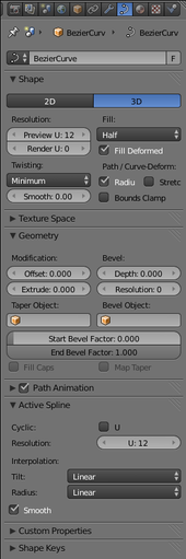
Look in the Curve Context
![]() in the Properties window, for the Geometry panel. There you should see two editable fields with the title “Bevel:” above them, one labelled “Depth:” and the other “Resolution:”. Try setting the depth to something like 0.1.
in the Properties window, for the Geometry panel. There you should see two editable fields with the title “Bevel:” above them, one labelled “Depth:” and the other “Resolution:”. Try setting the depth to something like 0.1.
::在属性窗口的曲线上下文中,查看几何面板.在那里,你应该看到两个可编辑的字段,上面标题为 Bevel:,一个标记为 Depth:,另一个标记为 Resolution:.尝试将深度设置为 0.1.
Now your curve is no longer a simple line. It should have a V-shaped cross section, perhaps like a piece of bent angle iron.
::现在你的曲线不再是简单的直线,它应该有V形的截面,
Now try increasing the “Resolution:” value, and you should see the V cross section start to smooth out, until at about a resolution of 2 or 3, it looks like a curved half pipe.
::现在试着增加"分辨率:"值, 你应该看到V截面开始平滑, 直到大约在2或3分辨率, 它看起来像一个曲的半管.
Now look further up, in the Shape panel. There should be a popup menu with the title “Fill:” above it; for a 3D curve, by default the item selected is “Half”. Try the “Front” and “Back” items, and you should see that these give you just halves of your half pipe.
::现在,在"形状"面板上方,应该有一个弹出菜单,上面标题为"填:";对于3D曲线,默认选择的项目是"半".尝试"前"和"后"项目,你应该看到这些只给你半管的半部分.
Now try “Full”, and your half pipe should now be a complete pipe.
::现在试试"全"吧,你的半管应该是完整的管.
You can also join the ends together by checking the “Cyclic: U” box under the Active Spline panel.
::您也可以通过在主动分线面板下勾选"循环:U"框将端子连接在一起.
Start and End Bevel Factors:
These reduce the extent of the bevel shape, so that instead of extending the full length of the curve, they go from and to the specified fractions of the length. These become more useful when the cross section of the shape is no longer uniform, when you apply a custom taper (below).
::起点和终点形因素:这些减少了形的范围,因此,它们不是延伸曲线的全部长度,而是从和向长度的指定部分.这些变得更有用,当形状的横截面不再均时,当你应用定制的形 (下面).
Now change the curve to 2D. The Fill options now become “Both”, “Front”, “Back” and “None”, where “Both” is like the “Half” setting for 3D curves. Note there is no equivalent of “Full”. But there is a new feature: if you check the “Cyclic: U” box, it will fill in the entire interior of the curve!
::现在将曲线更改为2D. 填充选项现在变成了Both,Front,Back和None,其中Both就像3D曲线的Half设置. 注意没有相当于Full. 但有一个新功能:如果你勾选了Cyclic:U框,它将填充曲线的整个内部!
Try this with a Bézier circle or a NURBS circle, and you should get a pancake-like object. For added flavour, give it a nonzero Extrude value, and this will make the shape even thicker.
::试用贝齐尔圆或NURBS圆,你应该得到一个饼形状的物体.为了增加味道,给它一个非零的挤出值,这将使形状更厚.
Custom Bevel
::定制的
Now we will try using another curve to supply the cross section. Add a Bézier circle shape. TAB into Edit mode. Now, select
just the end points of the handles
(
not
the control points themselves). In the Pivot Point menu, select “Individual Origins”. Now S cale down to 0.4.
::现在我们将尝试使用另一条曲线来提供截面. 添加贝齐尔圆形. 切换到编辑模式. 现在,只选择手柄的末端点 (而不是控制点本身). 在Pivot Point菜单中,选择"个人起源". 现在将Scale缩小到0.4.
The result should be something close to a square, but with rounded corners.
::结果应该是接近正方形的东西, 但角落是圆的.
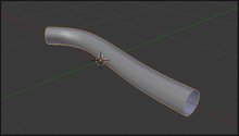
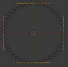
Go back to your first curve, and find the field titled “Bevel Object:” in the Geometry panel in the Curve Context
![]() properties. Click on it, and a popup menu should appear, and you should see the name of the second curve (e.g. ”BezierCircle”). Select that name, and you should see your bevelled curve immediately take on the cross-section of the new curve.
properties. Click on it, and a popup menu should appear, and you should see the name of the second curve (e.g. ”BezierCircle”). Select that name, and you should see your bevelled curve immediately take on the cross-section of the new curve.
::回到你的第一个曲线,在曲线上下文属性中的几何面板中找到标题为"凸物体:"的字段.点击它,应该出现一个弹出菜单,你应该看到第二个曲线的名称 (例如"BezierCircle").选择该名称,你应该看到你的凸曲线立即取代新曲线的截面.
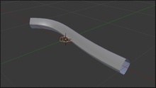
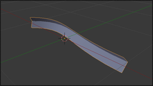
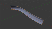
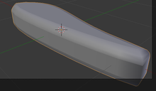
In fact, you may find the bevel object is a bit large; select it and, while still in Object mode, S cale it by a factor of 0.1. The result should appear something like this.
::实际上,你可能会发现形对象有点大;选择它,并且在Object模式下,将其加大0.1的因子.结果应该是这样的.
|
|
Only a curve can be used as a bevel.
In particular, meshes won’t work, but if necessary you can convert a mesh to a curve and then use that as the bevel shape.
|
Select the second curve again, go into Edit mode, and try messing around with the control points: you should see your changes immediately get reflected in the shape of the bevelled curve. You may find that the orientation of the second curve doesn’t coincide with the orientation of the bevel cross-section. This is easy to fix, because any change you make to the rotation and position of the second curve
in object mode
will have no effect on its use as a bevel, so you can freely reorient and reposition it to make it easier to match its shape up with the bevel cross section. (Scaling does, however, have an effect.)
::再选择第二个曲线,进入编辑模式,并尝试与控制点混:你应该看到你的变化立即得到反映在斜面曲线的形状.你可能会发现第二个曲线的方向不与斜面截面的方向一致.这很容易修复,因为你对对象模式中的第二个曲线的旋转和位置的任何变化都不会对其作为斜面的使用产生影响,因此你可以自由地重新定位和重新定位它,以便使其更容易与斜面截面匹配. (但是,缩放有影响)
|
|
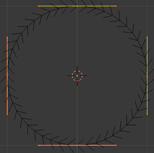
Tilt and Radius:
Go back to the first curve, and try the radius-scaling ALT + S and tilting CTRL + T functions you previously learned about. You will see that they affect the scaling and orientation of the bevel cross-section along the curve.
|
Custom Taper
::定制的缩水器
Now try adding a
third
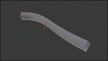
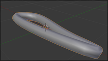
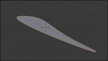
curve object. (As with custom bevels, only curve objects will work.) Go back to your first curve, find the “Taper Object:” field (it should be next to the “Bevel Object:” field you’ve already used), and select the name of your newly-added curve. The bevelled shape will now most likely squish down in a most peculiar way. Select your third curve, that you are using as a taper, and go into Edit mode. Now try adjust control points, and observe the effect on the bevelled shape: what you should find is that the object-local Y-coordinate of each control point governs the thickness of the bevelled shape at the corresponding position along the shape given by its X-coordinate, while the object-local Z-coordinate doesn’t have any effect.
::现在尝试添加第三个曲线对象. (就像自定义的形一样,只有曲线对象才有效.) 回到你的第一个曲线,找到"Taper Object:"字段 (它应该在你已经使用的"Bevel Object:"字段旁边),并选择你新添加的曲线的名字. 形现在很可能以一种非常奇特的方式压缩. 选择你作为一个形使用的第三个曲线,然后进入编辑模式. 现在尝试调整控制点,并观察形形状的影响:你应该发现每个控制点的对象-局部Y坐标控制着 X 坐标给定的形状沿着相应位置的形状的厚度,而对象-局部 Z 坐标没有任何影响.
As with the bevel shape, you can freely rotate and reposition (and this time, even rescale) the taper shape
in object mode
, and it will have no effect on its taper function: only alterations of the control points in edit mode have an effect.
::与形一样,在对象模式下,您可以自由旋转和重新定位 (这一次甚至重新缩放) 形,并且它不会对其形功能产生影响:只有编辑模式下控制点的改变才会产生影响.
|
|
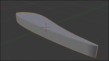
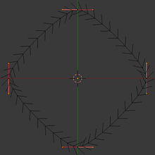
Tilt still works.
Try ALT + S and CTRL + T on the first curve as before; you should find that the former is now ignored (the size of the cross section being completely governed by the taper shape), but the latter still works.
|
|
|
The taper object should not have its own nonzero bevel or extrude settings.
This only confuses the issue.
|