Blender 3D:零基础到专业级-单元2:基本建模和着色
Understanding the Curve Modifier
::了解曲线修饰器
The
curve modifier
lets you use a curve shape to deform a mesh. The mesh will follow every twist and turn of the curve as far as it can bend, depending on how many vertices it has—clearly, the more vertices there are, the more faithfully it can follow the curve.
::曲线修饰器允许您使用曲线形状来变形网格.网格将按照曲线的每一个转折,尽可能曲,这取决于它有多少顶点显然,有越多的顶点,它可以更忠实地遵循曲线.
The curve modifier is also very easy to confuse yourself with if you’re not careful in how you set it up. A common situation is you try to move the deformed object in one direction, but it ends up moving in a completely different direction! This happens when you choose a deformation axis that doesn’t correspond to the predominant orientation of the points in the curve.
::曲线修饰器也很容易让你迷,如果你不小心设置它.一个常见的情况是你试图将变形物体移动在一个方向,但它最终移动在一个完全不同的方向!这发生在当你选择的变形轴不符合曲线中各点的主导方向时.
There are in fact some predictable rules that govern the behaviour of the curve modifier. Once you understand these rules, you shouldn’t need to keep trying different things at random to try to achieve the effect you want, you should be able to go straight for it.
::实际上,一些可预测的规则控制了曲线修改器的行为.一旦你了解了这些规则,你就不需要随机尝试不同的东西来尝试达到你想要的效果,你应该能够直接去做.
A Simple Example
::一个简单的例子
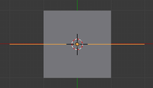
Let’s do an illustrative example to clarify things. Start a new Blender document; delete the default cube, and add a grid object instead, with the default 10×10 subdivision to give it plenty of vertices that can be deformed. Also add a path curve on top of it—this will give you a NURBS curve with 5 points, initially in a straight line. The result should look like at right.
::让我们做一个说明性的例子来澄清一些事情. 开始一个新的Blender文档;删除默认的立方体,并添加一个网格对象,默认的10×10分区给它很多可以变形的顶点. 还添加一个路径曲线在它的顶部. 这将给你一个NURBS曲线5点,最初在一条直线. 结果应该看起来像右边.
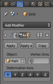
Now RMB on the grid, go to the Modifiers Context
![]() in the Properties window, and add a new Curve modifier which you will find in the "Deform" column. Click under "object" in the empty box and choose "NurbsPath".
in the Properties window, and add a new Curve modifier which you will find in the "Deform" column. Click under "object" in the empty box and choose "NurbsPath".
::现在在网格上,转到"属性"窗口中的"修改器上下文",然后在"变形"列中添加一个新的曲线修改器. 在空框中单击"对象"并选择"NurbsPath".
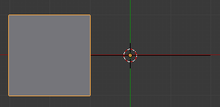
The grid object should immediately jump a little way in the direction of the negative X-axis. Why?
::网格对象应该立即跳到负X轴的方向.
|
|
Rule One:
The offset of the
first
point on the curve
in its local coordinate system
is also used to offset the origin of the deformed shape.
|
If you select the curve and TAB into Edit mode, you should see that, while the origin of the curve’s local coordinate system (the fat orange dot) is in the middle of the curve, the first point (the one at the end of curve in the same direction that the “centipede legs” are pointing) has a negative X-coordinate. Select just that point, and from the Snap menu SHIFT + S , do “Cursor to Selected”. Now TAB back into Object mode, and from Object→Transform do “Origin to 3D Cursor”. This will adjust the origin of the curve’s local coordinate system to that first point (keeping the curve itself in the same place), whereupon the grid object should jump back to its original location.
::如果您将曲线和TAB选择到编辑模式,您应该看到,虽然曲线的本地坐标系统的起源 (脂肪色点) 位于曲线的中间,但第一个点 (在曲线末端的,与百足指向的方向相同) 具有负X坐标.只选择该点,从快速菜单SHIFT + S,执行Cursor到Selected.现在TAB回到对象模式,从Object→Transform执行Origin到3D Cursor.这将调整曲线的本地坐标系统的起源到第一个点 (保持曲线本身在同一位置),然后对象应该跳回到原位置.
|
|
Corollary to Rule One:
You will make things a lot simpler for yourself if you change the origin of the deforming curve to coincide with its start point.
|
You can of course freely move around, add and delete the other points. Just be sure to keep that first point always at the origin of the curve.
::您可以自由移动,添加和删除其他点,但请确保始终保持在曲线的原点.
Now look at the settings for the Curve modifier. Notice those six buttons under “Deformation Axis:”?
::现在看看曲线修改器的设置. 留意在"变形轴"下的六个按:
|
|
Rule Two:
The Deformation Axis is interpreted according to the
local coordinate system of the deforming curve
.
|
When a path curve is created, all its points initially lie along its local X-axis. Since the default for the Deformation Axis is “X”, all works pretty much as you expect. If the two do not coincide, then weird things happen when you try moving things around.
::当路径曲线被创建时,其所有点最初都沿着其局部的X轴.由于变形轴的默认值是X,所有工作都很像你预期的那样.如果这两者不一致,那么当你试图移动物品时会发生奇怪的事情.
If you
really
want to mess around, you could go into Edit mode on the curve, select all its points, rotate them to, say, orient them along the local Y-axis, then get out of Edit mode, select the deformed mesh, and change the Deformation Axis on its modifier to Y, and things should still work consistently. But why bother?
::如果你真的想搞,你可以进入曲线的编辑模式,选择所有的点,旋转它们,说,沿着本地Y轴定向它们,然后退出编辑模式,选择变形网格,并将其修饰器上的变形轴更改为Y,事情应该仍然保持一致.
|
|
Corollary to Rule Two:
For simplicity, ensure that the Deformation Axis corresponds to the primary orientation of the points of the deforming curve
in its local coordinate system
. Otherwise, the deformed mesh will be
rotated from its undeformed orientation
, and will
go off at a completely different angle
when you try to move it.
|
As long as you obey the above rules, you can move, rotate and scale the deforming curve
in object mode only
as much as you like, and the deformation will still behave in a reasonable fashion. Of course, you can do what you like to the deformed mesh in object or edit modes, and this will still be true.
::只要你遵守上述规则,你只能在对象模式中随心所欲地移动,旋转和缩放变形曲线,而变形仍然会以合理的方式表现.当然,你可以在对象或编辑模式中对变形网格做你喜欢的事情,这仍然是真的.
|
|
Rule Three:
The effect of the deformation corresponds to the relative positions of deforming curve and deformed mesh in world coordinates.
|
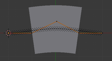
Select the curve, TAB into Edit mode, select the middle point, and move it a little to one side, as at right. You should see the grid mesh immediately bend in a corresponding way.
::选择曲线,将TAB转换为编辑模式,选择中间点,并将其稍微移向一侧,如右图.
Now TAB into Object mode, select the mesh, and move G it around: notice how it tries to follow the shape of whatever part of the curve lies nearest to it. What shape does it take when you move it off an end of the curve? How about to one side?
::现在,我们将TAB转入对象模式,选择网格,并将G移动一下:注意它如何试图跟随曲线中最接近它的任何部分的形状. 当你将它移到曲线的末端时,它会采取什么形状? 如何移到一边?
Alternatively, you can similarly drag the curve instead of the mesh, and the same thing will happen: it is only their relative positions that governs the actual deformation.
::另一种方法是,你也可以类似地拖动曲线而不是网格,
Also try changing the scaling radius ALT + S and tilt angle CTRL + T on particular curve points: note how the former causes the deformed mesh to get wider and narrow at those points, while the latter makes it tilt from side to side.
::试试在特定的曲线点上改变缩放半径ALT+S和倾斜角度CTRL+T:注意前者如何使变形网格在这些点上变得更宽和更窄,而后者使其从侧向侧倾斜.
Another Example
::另一个例子
Setting up your Mesh
::设置您的网格
While this example will be done with a cone primitive, you can use the default cube or another shape of your choosing so long as it can be loop subdivided along the axis you wish to curve. Delete the default cube if you're not going to use it as your base mesh, and add your chosen primitive. In this example, we'll be using a Cone.
::虽然这个例子将用形原始函数来做,但你可以使用默认的立方体或你选择的其他形状,只要它可以沿你想要曲线的轴进行循环分类.如果你不想用它作为你的基网,请删除默认的立方体,然后添加你选择的原始函数. 在这个例子中,我们将使用形.
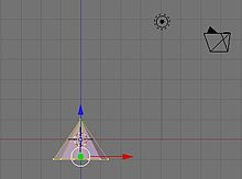
Do everything with the 3D cursor at the center.
::让我们把3D指针放在中心.
-
Set your view to the X-Y Axis (Top View) by pressing
NUM7
, the 7 on the keypad.
::通过按键盘上的NUM7和7来设置XY轴 (顶部视图) 的视图. -
Press
Shift+A >
Mesh
>
Cone
::按下Shift+A > 网格 > 圆形 -
A smaller number of vertices are needed, since this cone will become just the tip of the finished shape.
::需要更少的顶点, 因为这个圆将成为完成形状的尖端. -
Reduce the number of vertices to 12.
::将顶点数减少到12个. -
Press
TAB
to enter Edit Mode, or choose Edit Mode from the bottom of the 3D viewport.
::按TAB进入编辑模式, 或选择从3D视图端底的编辑模式. -
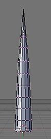
Switch views to the Z-X Axis by pressing
NUM1
(1 on the keypad). Your screen should now look something like the picture at left.
::通过按键盘上的 NUM1 (1),将视图切换到 Z-X 轴. 您的屏幕现在应该看起来像左边的图片. -
If your cone is selected (one or more vertices are yellow) press
AKEY
(Select/Deselect All) until they are deselected.
::如果您的圆已选定 (一个或多个顶点为黄色),请按键AKEY (选择/删除所有) 直到它们被删除. -
Select the point of your Cone with the
RMB
and drag it upwards with the blue arrow. You can hold down the
CONTROL
key if you want to constrain the scaling to set units. For this example, 5 squares of height were added to the cone.
::选择你的带人民币的点,用蓝色箭头将其拉上.如果你想限制缩放以设置单位,你可以按住控制键.在这个例子中,增加了5个高度的方形.
Subdividing the Cone
::锥体的分类
-
Go to front view by pressing
NUM1
::通过按NUM1进入前视图
The best way to do it is by selecting the side edges and subdivide them by pressing
WKEY
then clicking on
Subdivide
, after that you can select the number of cuts you want. You need at least "5" segments. The more segments you have, the smoother your curved cone will be. be sure you have "Limit selection to visible off" and to first deselect all "A key" and you are in "edge select" mode
::最好的方法是选择边缘并按下按键分开,然后点击分开,然后你可以选择所需的切割数. 你需要至少"5"段. 你有多段,你的曲线将是越光滑. 确保你有"限制选择可见的关闭"和首先取消选择所有"A键",你在"边缘选择"模式
-
You can also do: still in Edit Mode, press the
NUM8
repeatedly to rotate your view to the underside of your cone. Select the center vertex of the circle, and hold down
CONTROL
, then press the
+KEY
on the keypad. This will select all of the adjacent vertices of the base. Then extrude using the
EKEY
Pull the new vertices away from the cone a distance at the Z-axis and click the
LMB
to set them in place. Press the
SKEY
and widen the new base of the cone a bit.
::您还可以:在编辑模式下,按 NUM8 按多次,将视图旋转到形的下面.选择圆的中心顶点,按住 CONTROL,然后按键盘上的 +KEY.这将选择底座的所有相邻顶点.然后使用 EKEY 挤出.将新的顶点从形拉到 Z 轴上的距离,然后点击 LMB 设置它们.按 SKEY,稍微扩展形的新底座.
Making a Curve
::如何改变生活
-
In Object Mode, Z-X orientation ('
NUM1'
), make sure you have nothing selected and press
Shift+A
>
Curve
>
Bezier Curve
::在对象模式,Z-X定向 ('NUM1'),确保没有任何选项,然后按Shift+A>Curve>Bezier Curve -
Rotate your curve 90° (holding down the
CONTROL
key to make it rotate in 5° intervals) Note- or just R-KEY and then type 90, so that it lines up with your cone. Move it off to one side so that its not hidden by your cone.
::旋转你的曲线90° (按住控制键使它在5°间隔旋转) 注意-或只是R-KEY然后输入90以使它与你的圆对齐.将它移到一边,这样它不会被你的圆隐藏. -
Go into "wireframe"
::进入"线框" -
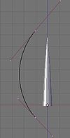
Grab the center vertex of each end and adjust its rotation (
RKEY
) until you have a nice shallow dome shape.
::抓住每个端的中心顶点, 调整其旋转 (RKEY), 直到你有一个漂亮的浅圆顶形状. -
Scale the curve in size (
SKEY
) until it is larger than your cone.
::缩小曲线的尺寸 (SKEY) 直到它大于你的圆. -
The name is highlighted in the "Outliner" Window: "BezierCurve"
::这个名字在"Outliner"窗口中突出显示:"BezierCurve"
Applying the Curve to the Mesh
::应用曲线在网格上
-
Select the cone in Object Mode. Choose in the "Properties" Header the "modifiers" tab and click "Add Modifier"
::在"属性"标题中选择"修改器"选项卡,然后单击"添加修改器" -
Click the
Add Modifier
button and choose
Curve
from the popup list.
::单击添加修改器按, 从弹出列表中选择曲线. -
Under Object tick the empty box, and select the name of the "Bézier Curve" (it will be "BezierCurve" without the quotations if you left it as the default.)
::在Object中勾选空框,并选择"Bézier曲线"的名称 (如果您将其作为默认值,则将其变成"BezierCurve"而没有引号). -
Notice the six buttons underneath, They are
X, Y, Z, -X, -Y, -Z
. They affect which plane the curve deforms. For this example, you'll need to select the
X
button.
::值得注意的是,下面的6个按是X,Y,Z, -X, -Y, -Z.它们影响曲线变形的平面. -
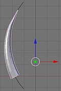
Move your Cone so that it overlays the curve in the '3D View" windows, and notice how it follows the Bézier Curve.
::移动你的圆,使它覆盖3D视图窗口中的曲线,并注意它如何遵循贝济埃曲线. -
You can modify the Bézier Curve as well as the cone repeatedly until you are happy with the design.
::您可以多次修改贝齐尔曲线和形,直到您对设计感到满意. -
If you switch to Edit Mode, notice that the cone returns to its straight orientation.
::如果切换到编辑模式, 您会注意到圆回到了直线方向. -
To apply the deformation to the mesh permanently, in the Modifiers panel, click the
Apply
button next to your Curve modifier.
::在修改器面板中, 单击"应用"按. -
Move the curve up 'till the cone is around the curve
::向上移动曲线,直到圆绕曲线