Blender 3D:零基础到专业级-单元2:基本建模和着色
Overview
::概述
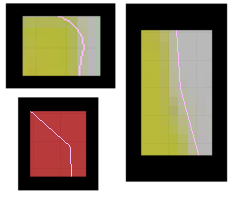
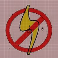
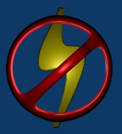
We will be using this graphic as a template for a 3d logo, tracing it, then discarding the 2d image.
(Click thru to get the larger sized version, for you to follow along with)
::我们将使用这个图像作为一个模板,为一个3D标志,跟踪它,然后丢弃2D图像. (点击通过以获得更大的尺寸版本,让你跟随)
Load the background image into blender
::将背景图像加载到混合器中
Basics of the background image panel
::背景图像面板的基本知识
If you haven't already done so, open blender and select one of the orthogonal view angles by pressing
NUM7
(top),
NUM3
(side), or
NUM1.
(front). At the bottom of the 3D viewport on the left, there are some menus, click
View
->
Background Image
::按下NUM7 (顶部),NUM3 (侧面),或NUM1. (前面). 在左侧的3D视图窗口的底部,有一些菜单,点击查看 -> 背景图像
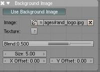
A small window will appear containing just one button marked
use background image
; click this button. A few more buttons will appear. One of them says
image:
and has a small button with a picture of a folder on it; click this button. You are now presented with a file selection screen. Using the navigation techniques from the previous tutorials, find your 2D jpeg image on your computer, click the file in the list once then click the
Select Image
button at the top right of the screen.
::现在您将看到一个文件选择屏幕. 使用上一篇教程的导航技术,在计算机上找到您的2D jpeg 图像,单击列表中的文件,然后单击屏幕右上方的选择图像按. 您可以在此处选择文件,然后选择图像. 您的文件选择屏幕将显示一个小窗口,其中包含一个按标记使用背景图像; 点击此按. 更多的按将出现. 其中一个说图像:并有一个小按上面有一个文件的图片; 点击此按. 您现在会看到一个文件选择屏幕. 使用上一篇教程的导航技术,在您的计算机上找到您的2D jpeg 图像,单击列表中的文件一次,然后点击屏幕右上方的选择图像按.
Noob note: The image is only displayed in orthogonal view. If perspective view is enabled, toggle to orthogonal view by pressing
NUM5
.
(The image will not be rendered as it is not part of your scene.)
::图像只显示在直角视图中. 如果启用了透视视图,请按NUM5切换到直角视图. (图像不会染,因为它不是您的场景的一部分.)
Once a background is selected you'll have a dialog like this one. (Note: This tutorial was originally generated from Blender v2.37. v2.43 has been added - older versions may differ.) The background dialog buttons are described below:
::一旦选择了背景,您将会看到这样一个对话框. (注意:本教程最初是从Blender v2.37生成的.已经添加了 v2.43 - 旧版本可能有所不同.) 下面描述了背景对话框按:
Details of the background image panel
::背景图像面板的详细信息
The
![]() is a toggle button that turns display of the image on or off. Turning the button off will not clear the settings; it just hides the image. When you turn the button on again, your previous settings are back. Try it - click the button a few times. In v2.43 the equivalent button is the
is a toggle button that turns display of the image on or off. Turning the button off will not clear the settings; it just hides the image. When you turn the button on again, your previous settings are back. Try it - click the button a few times. In v2.43 the equivalent button is the
![]() button.
button.
::按是一个切换按,可以将图像的显示开启或关闭.关闭按不会清除设置;它只是隐藏图像.当你再次打开按时,你的以前的设置会恢复.试试 - 点击按几次.在v2.43中,相应的按是按.
Image selection is controlled on the row labeled
![]() . There are 2 buttons, a text box, and a final button. The first button
. There are 2 buttons, a text box, and a final button. The first button
![]() is used for browsing for an image. The 2nd button
is used for browsing for an image. The 2nd button
![]() is for selecting an image from a history list. (This will be empty for the first time. Selecting it now will display the image you currently have selected.) The text box
is for selecting an image from a history list. (This will be empty for the first time. Selecting it now will display the image you currently have selected.) The text box
![]() allows typing in the file directly. The
allows typing in the file directly. The
![]() button removes the current background image. Version 2.43 is the same with the addition of the
button removes the current background image. Version 2.43 is the same with the addition of the
![]() button that refreshes the image or movie, and the
button that refreshes the image or movie, and the
![]() button which shows the number of users of the image block.
button which shows the number of users of the image block.
::图像选择控制在标记的行.有2个按,一个文本框和一个最后的按.第一个按用于浏览图像.第二个按用于从历史列表中选择图像. (这将是空的.现在选择它将显示您当前选择的图像.) 文本框允许直接输入文件.按删除当前的背景图像.版本2.43是相同的,添加了刷新图像或电影的按,以及显示图像块用户数量的按.
The third row is called Texture and will not be used for this tutorial.
::第三行是"纹理", 不会在本教程中使用.
The fourth line, labeled
blend
controls the transparency of the background image with a slider. A setting of 0 is completely solid and 1 is completely transparent. You can adjust it by clicking left or right of the knob for gradual changes, clicking and dragging on the slider for rough settings or clicking directly on the
blend
text for numeric entry.
::第四行,标记为混合,通过滑块控制背景图像的透明度.设置0是完全固体,而1是完全透明.您可以通过点击按的左或右进行渐进的更改,点击和拖动滑块进行粗略设置,或直接点击混合文本进行数字输入来调整.
The use of the blend function will become obvious once we start tracing our logo. For now, play around with it, see how it changes the image, and put it back to the 0.500 default.
::混合函数的使用将会很明显, 一旦我们开始追踪我们的标志. 现在,玩它, 看看它如何改变图像, 并把它回到0.500默认值.
The fifth line,
size
, controls the size of the image. This size setting is independent of the zoom for the 3D view window. To see how the size works move the default cube off to the side so that you can see both the cube, the background dialog and the background image. Now watch both the cube and image as you change the size. Notice how the image changes size but the cube doesn't? Now press
NUM+
and
NUM-
to change the view's zoom. Now both the cube and image change size.
::第五行,size,控制图像的大小.这个大小设置是独立的3D视图窗口的变焦. 为了看看大小如何工作移动默认立方体到一边,这样你就可以看到立方体,背景对话框和背景图像. 现在看立方体和图像,当你改变大小. 注意到图像如何变大,但立方体没有? 现在按NUM+和NUM-改变视图的变焦. 现在立方体和图像都改变大小.
The final row controls the X and Y offset for the image. These controls move the image up and down (Y) or left and right (X). These settings can be useful if you need to reposition the image from the default position. Like the size, these offset values are independent of the view. As you change the offset values the cube you added earlier won't move. Now scroll the view using by clicking and dragging the
SHIFT MMB
and notice how the cube and image move together?
::最后一行控制图像的X和Y偏移.这些控制将图像向上和向下移动 (Y) 或左和右移动 (X).如果您需要从默认位置重新定位图像,这些设置可能很有用.像大小一样,这些偏移值与视图是独立的.当您更改偏移值时,您先前添加的立方体不会移动.现在通过单击和拖动SHIFT MMB滚动视图,并注意到立方体和图像如何一起移动.
Once you start tracing the image you won't be using the size or offset setting.
::您将无法使用尺寸或偏移设置.
Details for version 2.6X
::版本 2.6X 的详细信息
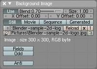
the check box left to the title indicate if you can see the image or not. the
Axis
menu indicate in what views you could see the image.
::标题左边的选项框显示您是否可以看到图像. 轴菜单显示您可以在哪些视图中看到图像.
the button
Image
and
Movie Clip
indicate of course if you use a Image or a Movie.
::按图片和电影片段表示您使用的是图片还是电影.
the button to left of the text box allows to choose the image from the exist, the text box say the name of the image, the F botton make the image a fake user, the folder sign allow to upload an image, and the X sign delete the link to the picture.
::文本框左边的按允许从存在中选择图像, 文本框说图像的名称, F按使图像成为假用户, 文件标志允许上传图像, 和 X标志删除图片链接.
The
blend
slider mentioned above is now called
Opacity
. The image will be completely transparent when the opacity value is zero, and fully opaque when the value is one.
::上述的混合滑块现在被称为Opacity.当不透明度值为零时,图像将完全透明,当值为一时则完全不透明.
Delete the cube
::删除立方体
Delete the cube (select it, press
XKEY
and select
All
from the
Erase
menu), and set the size so that the entire image is viewable. Then set both the X and Y offsets to 0.
::删除立方体 (选择它,按 XKEY 并从删除菜单选择全部),并设置大小,使整个图像可见. 然后将 X 和 Y 偏移设置为 0.
Set the view to top view (
NUM7
) for the rest of the tutorial!
::设置视图顶部视图 (NUM7) 对于教程的其余部分!
Finally minimize the Background Image dialog. You'll only need it to adjust the blend setting until you finish tracing.
::最后将背景图像对话框缩小到最小. 您只需要调整混合设置,直到您完成追踪.
Introducing the Bézier Curve
::介绍贝齐尔曲线
The
Bézier Curve
allows drawing graceful, complex curves and only requires a few points. Specifically, it only requires 4 points for a curve: two end points and two control points.
::贝济埃曲线允许绘制优雅,复杂的曲线,只需要几个点.具体来说,它只需要4个点曲线:两个终点和两个控制点.
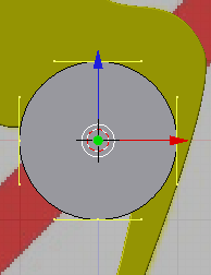
For the moment set the blend to 1 on the Background Image dialog. With the center of the 3D view still selected, press
SPACE -> Add -> Curve -> Bézier Curve
. Alternatively you can use the
Add
menu at the top of the screen or press
SHIFT -> AKEY
to jump directly to the add menu. Be sure to be in EDIT MODE not OBJECT MODE.
::现在在背景图像对话框中将混合设置为1. 仍然选择3D视图的中心,按空格 -> 添加 -> 曲线 -> 贝齐尔曲线. 或者您可以使用屏幕顶部的添加菜单或按 SHIFT -> AKEY直接跳到添加菜单. 确保处于编辑模式而不是对象模式.
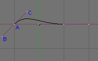
Unlike the traditional Bézier Curve each Bézier vertex has 3 points. I've labeled the 3 points for the left vector: A, B and C.
::传统的贝济尔曲线不同,每一个贝济尔顶点有3个点. 我已经给左向量标记了3个点:A,B和C.
Just like any other vertex you select the control points and the end points with
RMB
and move them with standard commands like
GKEY
,
SKEY
,
EKEY
or
RKEY
. if you wish to rotate, scale, or move the whole curve, then select all the vertices on the curve using one of the various selection methods, and then use the
GKEY
,
SKEY
, or
RKEY
::像任何其他顶点一样,您选择控制点和终点用人民币,并使用标准命令移动它们,如GKEY,SKEY,EKEY或RKEY. 如果您希望旋转,缩放或移动整个曲线,然后使用各种选择方法之一选择曲线上的所有顶点,然后使用GKEY,SKEY或RKEY
Point A
is an end point. The curve will always go through this point.
Points B and C
are control points. These points influence the path of the curve as it leaves
Point A
. Because the path stops at
A
,
Point B
has no real effect on the path. Instead
B
is currently locked with
C
. (If you move either
B
or
C
, the other will move.) We will
fix
Point B
to move independently a little later.
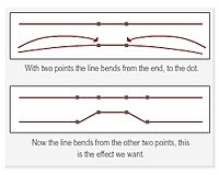
::点A是一个终点.曲线总是通过这个点.点B和C是控制点.这些点影响曲线离开点A的路径.因为路径在A停止,点B对路径没有实际影响.相反,B目前与C锁定. (如果你移动B或C,另一个将移动.) 我们稍后将B点固定在独立移动.
The control points have 2 effects on the path exiting the end point: direction and distance (these are termed slope and magnitude in math circles) from
Point A
. The direction will provide the direction that the path will follow when it leaves
A
and the distance will determine how long the path follows that direction before it starts making its way to the curve's next point.
::控制点对从终点出发的路径有两种影响:方向和距离 (在数学圈中称为斜率和大小) 从点A.方向将提供路径离开A时所遵循的方向,距离将决定路径在向曲线下一个点前遵循该方向的长度.
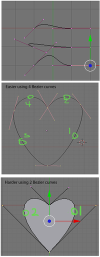
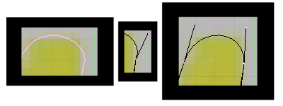
The example to the right shows how the control points influence the path of the curve. In the top picture, we see three curves. The top curve is the default curve. In the next curve down,
C
has been moved to give a drastically different direction. Notice how the path leaving
A
moves away from the other end point. The third curve, the distance was changed dramatically. Watch the path move much higher than the other two curves.
::右边的例子显示了控制点如何影响曲线的路径.在顶部图片中,我们看到三个曲线.顶部曲线是默认曲线.在下一个曲线中,C被移动以给出一个完全不同的方向.注意离开A的路径如何远离另一端点.第三个曲线,距离发生了显著变化.观察路径比其他两个曲线更高.
In the bottom example, I've built a heart shape using just the points shown.
Dragging the bottom end point down will make the shape closer to a leaf.
You'll be able to do the same at the end of this tutorial. Go ahead move around the points for the curve and see how they all interact. Get a good feel working with the curve and when you're ready we'll move on to tracing.
::在下面的例子中,我用所示的点构建了一个心形. 下面的末端点向下拉动将使形状更接近叶子. 在本教程的末尾,您将能够做同样的事情. 继续移动曲线的点,看看它们如何相互作用. 让你感受与曲线的工作,当你准备好了,我们将继续进行跟踪.
Now that you know how to work with a bezier curve set blend back to 0.5 on the Background Image dialog so we can start tracing.
::现在你知道如何使用贝齐尔曲线, 在背景图像对话框中将其调整为0.5
Modeling the lightning bolt
::模拟闪电
Rough Tracing
::粗略追踪
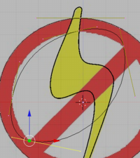
If you don't already have a curve add one now. It will help to move the curve to the center of the yellow lightning bolt.
::如果您还没有一个曲线, 现在添加一个. 这将有助于将曲线移到黄色闪电的中心.

The first step in tracing is to click the Polygon convert button on the curve tools panel. You'll find this in button on the
Buttons Window
. You may need to select the
Edit Panel
. Press
F9
if this panel isn't visible.
::追踪的第一步是点击曲线工具面板上的多边形转换按.你会在按窗口的按中找到这个.你可能需要选择编辑面板.如果这个面板不显示,请按F9.
In Blender 2.59, the 3D View panel's Tool Shelf (
T
) houses the Curve Tools, including Set Spline Type, from which you should select Poly. You must be in Edit Mode to reach the Curve Tools.
::在Blender 2.59中,3D View面板的工具架 (T) 包含曲线工具,包括设置分线类型,您应该从中选择Poly.您必须处于编辑模式才能访问曲线工具.
Noob Note:
The 'Curve Tool' panel will not appear if you don't have a bezier curve already placed. I learned this the hard way.
::如果没有一个比较好的曲线, 则"曲线工具"面板不会出现.
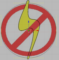
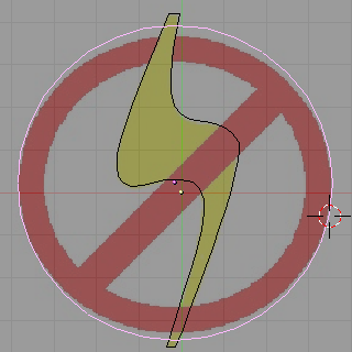
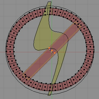
Next, move the vertices of the curve to the points shown in the image to the left. This is called Rough Tracing because you don't need to exactly trace the image.
::接下来,将曲线的顶点移到图片左边的点. 这叫做粗略追踪, 因为你不需要精确追踪图像.
You only need to approximate the image. Moving the vertices should be done using the instructions from the
Creating a Simple Hat
tutorial.
::移动顶点应该使用创建简单帽子教程中的指令.
Note: Selecting the best place to put a vertex is a bit of an art that you'll acquire as you work with curves. For now follow the arrows along the cutouts and place each of the vertices as shown.
::注意:选择最好的位置放置顶点是一个艺术的小部分,你会获得当你工作与曲线.现在沿着剪切沿着箭头,并放置每个顶点如图所示.
This tracing uses all the vertices of the polygon. Other cases, you'll need add or remove extra vertices by selecting the end point of your curve press
CTRL
and click
LMB
. At the place you clicked a new vertex will appear connected to your curve.
::这种跟踪使用了多边形的所有顶点. 在其他情况下,您需要通过选择曲线的终点,按Ctrl,点击LMB来添加或删除额外的顶点. 在您点击的地方,将会出现与您的曲线连接的新顶点.
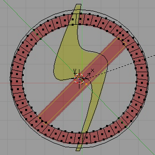
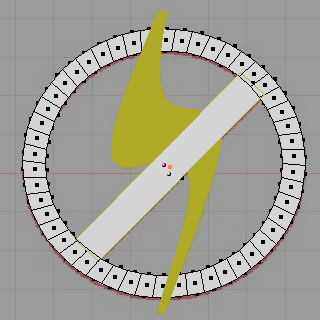
After moving the last vertex, we finish the rough tracing by pressing the Alt+
CKEY
to close the polygon. You should see an image similar to the one on the right. (If you only have an outline switch your view port shading to solid by pressing the
ZKEY
for now.)
::移动最后一个顶点后,我们通过按 Alt+CKEY 关闭多边形来完成粗略的绘图.您应该看到与右边相似的图像. (如果您只有一条轮,请暂时按 ZKEY 切换视图端口的遮为实体).
Question
: how do you close the polygon in blender 2.61?
Answer
_ ALT + CKEY pressing c key alone brings up circle select.
::问题:如何在混合器2.61中关闭多边形? 答案_ALT+CKEY单独按c键就会显示圆选.
Note: In Blender 2.63 and certain prior versions, the curve needs to be changed from 3D to 2D shape in order for the polygon to show up, else you get an error. This can be changed by going into Object Data and, under the Shape heading, switching the curve from 3D to 2D.
::注意:在Blender 2.63和某些之前的版本中,需要将曲线从3D转换为2D形状,才能显示多边形,否则会出现错误.可以通过进入Object Data,在Shape标题下,将曲线从3D转换为2D来改变.
Notice how the polygon doesn't cover all of the yellow of the bolt and how in some places the polygon fails to conform to the shape of the bolt. This is expected and should not be a cause for concern. We correct this in the next section.
::注意多边形不覆盖螺栓的所有黄色,以及多边形在某些地方不符合螺栓的形状.这是预期的,不应该引起关注.我们在下一节中纠正这一点.
Once you've finished several logos you should begin to get a feel for the required placement of vertices. Until then, here are some general guidelines to keep in mind:
::一旦你完成了几个标志,你应该开始感觉到顶点的必要位置. 在那之前,以下是一些一般指导方针要记住:
-
A gradual curve may only require a single vertex.
::一个渐进曲线可能只需要一个顶点. -
Tight curves will likely require two closely placed vertices.
::狭窄的曲线可能需要两个靠近的顶点. -
Curves may not require a vertex at all - you can define some curves using the control points of the adjacent vertices. We did this for both of the inside curves of the bolt above.
::曲线可能不需要顶点 - - 你可以使用相邻顶点的控制点来定义一些曲线.我们对上面的螺栓的两个内曲线做了这样的操作. -
Corners require a single vertex placed where the curve bends. A square, for instance, requires four vertices - one at each corner - to be modeled properly.
::角需要一个单一的顶点放在曲线曲的地方.例如,一个方形需要四个顶点 - 每个角落一个 - 才能正确建模. -
The end point of a curve will always be on the curve. So should all of the vertices you place.
::曲线的终点总是在曲线上. 你放置的所有顶点也应该如此.
We are now ready to move onto the next step modeling the logo.
::我们现在准备好进入下一步,
Polishing the Tracing
::磨练的痕迹
Press
ZKEY
to return to wire frame mode, then Press the
Bézier
convert button to convert the polygon back to a curve.
::按 ZKEY 返回线框模式,然后按 Bézier 转换按将多边形转换为曲线.
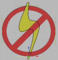
This will convert your polygon back into a curve. Nothing obvious will happen. If you look close, you should notice the number of points on the curve tripled. When you converted the curve back to a Bézier curve, Blender changed all of the polygon vertices to Bézier vertices. While the polygon vertex is a single point the Bézier vertex is made of an end point and 2 control points. So the extra points are the control points of the Bézier vertices. These control points are placed along the curve to produce the same shape as the converted polygon.
::这将把多边形转换成曲线. 显而易见的情况不会发生. 如果你仔细看,你应该注意到曲线上的点数增加了三倍. 当你把曲线转换成贝齐尔曲线时,Blender 将多边形的顶点全部更换为贝齐尔顶点. 虽然多边形的顶点是一个单点,但贝齐尔顶点由一个终点和2个控制点组成. 所以额外的点是贝齐尔顶点的控制点. 这些控制点沿着曲线放置,以产生与转换的多边形相同的形状.
Our job is to move the control and end points so that the curve follows the edge of the bolt. The trick is to move the 2 control points between adjacent end points to bend the curve to the edge of bolt. First, move the right control point of the top-left vertex. This should pull the curve from its end point to more closely match the line of our bolt. After placing this point, we move to the next control point following a clockwise direction around the bolt. Use the
RMB
to select the point you want to change and move it with
GKEY
to place it.
::我们的工作是移动控制点和终点,使曲线沿着螺栓的边缘. 技巧是移动两个相邻的终点之间的控制点,使曲线向螺栓的边缘曲. 首先,移动左上顶点的右控制点. 这应该将曲线从它的终点拉到更接近我们的螺栓的直线. 放置这个点后,我们将沿着针方向绕螺栓移动到下一个控制点. 使用人民币选择要更改的点并使用GKEY移动它来放置它. 设置一个控制点,然后将它移动到一个控制点,然后将它移动到一个控制点. 设置一个控制点,然后将它移动到一个控制点,然后将它移动到一个控制点,然后将它移动到一个控制点,然后将它移动
Noob Note:
if you wind up with pink lines when you select the contral handels, that means you hit
HKEY
by accident, and have put the control point in manual. to correct this hit
HKEY
again to put it back into "easy" or auto mode.
::操作指令:如果在选择控制指令时出现粉红色线条, 则表示您意外地按HKEY,
As you move the second point notice how the curve exiting the first end point is drawn away from the edge of the bolt being traced. We now have to adjust the first control point again to get that line back on track. This quickly turns into a balancing act adjusting each set of control points. The trick is to make smaller movements for each iteration of adjustments. Make a game of it and move the control points all along the bolt. Always move along the clockwise direction. This practice is not just for consistency, it keeps your place and ensures that moving a control point doesn't change a portion of the curve that you've already completed. In time you learn to move the first point only part of the way. Then moving the second brings the curve for the first into correct alignment.
::随着你移动第二点,注意如何从第一端点出口的曲线与被绘制的螺栓边缘相距.现在我们必须再次调整第一控制点以使该线重新回到正轨.这很快就变成了调整每一组控制点的平衡行为.技巧是为每次代调整做更小的动作.玩游戏并沿着螺栓移动控制点.总是沿着时钟针方向移动.这种练习不仅仅是为了一致性,它保持了你的位置,并确保移动控制点不会改变你已经完成的曲线的一部分.随着时间的推移,你学会移动第一点只是部分路径.然后第二个将第一位移动的曲线带入正确的对齐.
If you have some trouble aligning the curve to the edge of the bolt, consider adding a new point. There are two (at least) ways to accomplish this:
::如果您在将曲线与螺栓边缘对齐时遇到一些问题,请考虑添加一个新点.有 (至少) 两种方法可以实现这一点:
-
Select 2 points that surround the problem spot where you want a new vertex and click the Subdivide button on the Curve Tools 1 tool panel.
::选择两个点, 围绕着你想要一个新的顶点, 单击"Curve Tools 1"工具面板上的"Subdivide"按. -
If near an end point, Select it, press the
CKEY
to open the curve, then
Control+LMB
click to add a new point beyond the end of the selected final vertex. Press the
CKEY
to reclose the curve.
::如果接近终点,请选择它,按CKEY打开曲线,然后点击Control+LMB添加一个新的点在选择的最后顶点的尽头.按CKEY重新关闭曲线.
The new end point should be positioned and then you have to adjust the curve on both sides of the end point you move. Any time you move an end point be sure that the curve going into both adjacent (clockwise and counter-clockwise) end points still aligns with the edge of the bolt.
::必须在新端点的位置上,然后在移动的端点的两侧调整曲线.每次移动端点时,请确保进入相邻 (顺时针和反时针) 端点的曲线仍然与螺栓的边缘保持一致.
Once you've made the complete circuit around the bolt, you're ready for the final polishing of the edge of the curve. Press the
TAB
to switch to the object mode. This makes the polishing easier as Blender hides the points and lines for editing the curve. Now zoom in on the bolt's edge using the
NUM+
or
Control+LMB
drag. Use
Shift+MMB
drag the screen so that you closely observe the entire edge of the bolt while zoomed in closely. Look for places where the curve pulls away from the edge.
::一旦你完成了围绕螺栓的完整电路,你就准备好完成曲线边缘的最后抛光.按TAB切换到对象模式.这使得抛光更容易,因为Blender隐藏了编辑曲线的点和线.现在使用NUM+或Control+LMB拖动缩小螺栓边缘.使用Shift+MMB拖动屏幕,以便在缩小时仔细观察螺栓的整个边缘.寻找曲线从边缘拉开的地方.
Also look for sharp bends at each of the end points that should be smooth. You can see several defects that I found in my project after tracing the bolt. Switch back into edit mode to fix the curve and then go back into object mode to look for more defects.
::另外,在每个端点都需要找出的曲线,这些曲线应该是光滑的.在追踪螺栓后,你可以看到我在项目中发现的几个缺陷.回到编辑模式来修复曲线,然后回到对象模式来查找更多缺陷.
Sharp end points are adjusted by decreasing the angle between end point and the control points. Many times that is impossible to do, without messing up what you're trying to draw, so the other way is to add more curves by subdividing (
WKEY
-> subdivide )the existing curve between two end points, and playing with the control points to get a nice smooth curve,
::通过减少端点和控制点之间的角度来调整尖端点. 很多时候这是不可能的, 没有搞你想要画的东西, 所以另一种方法是通过分成 (WKEY -> 分成) 增加更多的曲线 两个端点之间的现有曲线, 并用控制点来获得一个很好的光滑曲线,
Places where the curve pulls away from the edge can be resolved by moving the control point closer to the edge. In the above image the curve was found to have been pulled away from the edge. This was fixed by moving the control point a little to the left.
::曲线偏离边缘的地方可以通过将控制点靠近边缘来解决.在上图中,发现曲线偏离边缘.通过将控制点稍向左移动来修复.
Here's the final polished curve for my project. It is shown in both edit mode and object mode so you can clearly see both the control and end points on the left and the curve to the right.
::这里是我项目的最后的光曲线. 它显示在编辑模式和对象模式,
Noob note:
In blender 2.37 and later (not sure of earlier versions) pressing the
HKEY
toggles the control points between free and aligned (Edit Mode). Free Control Points are good for sharp angles, and aligned are good for smooth curves. This shortcut is in the
Space -> Edit -> Control Points
menu.
::笔记:在混动器2.37及后版本 (不确定早期版本) 中,按HKEY将控制点切换到自由和对齐 (编辑模式).自由控制点适用于利的角度,对齐适用于光滑的曲线.这个快捷方式在空间 -> 编辑 -> 控制点菜单中.
This concludes the tracing of the bolt. All that remains is making the curve 3 dimensional, applying a material and positioning the final object. Before doing that, we will trace the circle in the next part of the tutorial. Save this project if you want to take a break before continuing. You'll need it on the next turorial.
::现在我们已经完成了螺栓的绘制.剩下的就是使曲线变得三维,应用材料并定位最终的物体.在做之前,我们将在教程的下一部分绘制圆圈.如果您想在继续之前休息一下,请保存此项目.您将在下一个图表中使用它.
Adding a Third Dimension
::增加第三个维度
First, give the object some depth. if you are in wirefame, hit
ZKEY
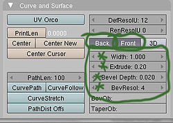
to go in to solid mode, then down on the editbuttons screen, locate the "Curve and Surface" panel, and set the following values:
::首先,给对象一些深度. 如果你在线名,按ZKEY进入固体模式,然后在编辑按屏幕下方,找到"曲线和表面"面板,并设置以下值:
-
Back and front buttons are selected (depressed), otherwise it will be see through.
::选择前后按 (压下),否则将会看到通过. -
Extrude: 0.2 (the height of the extrusion on either side)
::挤出:0.2 (挤出的高度在两侧) -
Bevel Depth: 0.02 (the radius of the round bevel applied to the extruded edge)
::形深度:0.02 (圆形形的半径应用于挤出边缘) -
BevResol: 4 (the number of subdivisions on the bevel curve)
::形解析度:4 (形曲线上的分区数)
Noob note:
In previous versions, Extrude and Bevel Depth were Ext1 and Ext2.
::笔记:在以前的版本中,挤出和板深度是Ext1和Ext2.
Noob note:
In versions 2.6x(possibly also 2.5x), go to
Properties panel --> Object Data --> Geometry
for these settings.
::在版本2.6x (也可能是2.5x) 中,请进入属性面板 --> 对象数据 --> 几何设置.
Now you can use your knowledge from earlier in this book to change the material and/or add texture to your logo. Feel free to rotate, add lighting, or whatever floats your boat. Don't forget to press
ZKEY
to toggle wireframe mode.
::现在你可以用本书上文的知识来改变材料和/或为你的标志添加纹理. 随时可以旋转,添加照明,或任何漂浮你的船. 别忘了按ZKEY切换线框模式.
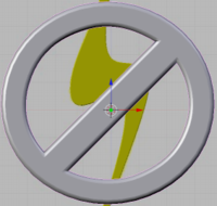
You should now have something that looks like the photo on the left.
::现在应该有像左边的照片一样的东西.
Modeling the red circle
::模拟红色圆圈
It will be helpful to make the lightning bolt distinct from the circle part of the logo, by applying a yellow material to it before continuing.
::在继续之前,将黄色材料涂在闪电与标志的圆部分之间, 这将有助于使闪电与标志的圆部分区别开来.
Method one is the easiest, so try it that way first.
::首先是最简单的方法,
Method 1 - using bezier circle
::方法1 - 使用贝齐尔圆
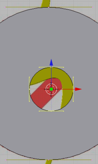
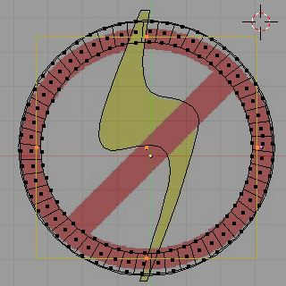
Outer circle
::外圈
Switch to object mode by hitting
TAB
if you aren't already there.
LMB
somewhere near the center of the background photo. Press
space -> Add -> Curve -> Bézier Circle
to add a closed bezier curve with four points forming a circle. If you are in solid draw type, switch to wireframe with
ZKEY
so you can see the underlying image better. Hit
SKEY
to scale the bezier circle to fit over the circle in the image. Again, if you are using one of the newer versions, you will have to switch the circle from
3D
to
2D
in the object panel.
::如果您还没有在图像中,请按TAB转换为对象模式.如果您还没有在图像中,请按背景图片的中心附近的某个位置的LMB.按空格 -> 添加 -> 曲线 -> 贝齐尔圆,以添加一个圆形的四点的闭式贝齐尔曲线.如果您是固体绘图类型,请使用ZKEY切换为线框,以便您可以更好地看到底层图像.按SKEY将贝齐尔圆缩小到图像中的圆形上.再次,如果您使用的是较新的版本之一,您将不得不在对象面板中将圆形从3D切换到2D.
Noob note:
You should stay in object mode for now, as it's easier to scale and move the bezier circle without having to keep track of which end points are selected.
::现在应该保持对象模式, 因为它更容易扩展和移动贝齐尔圆圈,
You will probably find that the bezier circle is not dead center on the sample logo so you will need to move it with
GKEY
to center it. You may need to scale it and move it several times to get it right. You will also find that the circle in the sample image is actually a slight oval, so scale and position the bezier circle, along the X axis, and Y axis, so that it touches the circle in the image on the left and right sides.
::你可能会发现贝济尔圆圈不是样本标志的中心,所以你需要用GKEY移动它以使其处于中心.你可能需要缩放它并移动它几次才能正确.你也会发现样本图像中的圆圈实际上是一个轻微的圆,所以缩放和放置贝济尔圆圈,沿X轴和Y轴,使其触摸图像中的圆圈在左侧和右侧.
Normally, you could then scale the circle and constrain it on the X and Y axis by using
SKEY
, but it turns out that the oval isn't regular anyway, so just select the point on the top and hit GKEY and then
XKEY
, or
YKEY
to move it around until it touches the top of the oval in the image. Then do the same for the bottom point and you should have a pretty good fit.
::通常,你可以通过SKEY缩小圆圈,在X和Y轴上限制它,但事实证明圆形并非正则,所以只需选择顶部的点,然后按GKEY,XKEY或YKEY,移动它直到它触及图像中的圆形的顶部. 然后对底部点做同样的事情,你应该得到很好的合适.
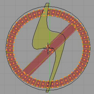
Inner half circle 1
::内部半圆1
Just to understand what's happening in the next steps, switch to solid view with
ZKEY
. As you can see, you now have a circle, but it's filled in the middle where you want to be able to see through it. To cut a hole out of the circle, be sure that the circle is selected, then hit
Shift+S
-> "cursor to selection, to put the cursor in the middle, switch into
edit mode
, if you're not already in it, and then
Space -> Add -> Bézier Circle
. A new circle will appear inside the larger circle. As you can see in solid mode, the new circle actually cuts its shape out of the larger circle surrounding it.
::为了了解下一步的情况,请使用 ZKEY 切换到固体视图. 如你所见,现在你有一个圆,但它在中间被填充,你希望能够透过它. 要切出圆的孔,请确保圆被选中,然后按 Shift+S -> "cursor to selection,将光标放在中间,切换到编辑模式,如果您还没有进入它,然后空间 -> 添加 -> Bézier Circle. 一个新的圆将出现在更大的圆内. 如你所见,在固体模式下,新的圆实际上是从周围的更大的圆中切割出来的.
Noob note:
make sure you are in Edit Mode or it will add the new Bézier circle without cutting it out of the existing one.
::确保您处于编辑模式,否则它将在没有切除现有的情况下添加新的贝齐尔圆.
Switch to wireframe mode with
ZKEY
so that you can see the underlying image again. Scale up the smaller circle so that it approximately fits the inner part of the circle in the image. Don't worry about getting it exact since you'll be manually moving all four points anyway. Move the bottom point of the bezier circle to the top left corner of the bar that crosses the circle.
::切换到线框模式使用ZKEY,这样你就可以再次看到底层图像.缩小小圆,这样它大致适合图像中的圆的内部部分.不要担心要准确,因为你无论如何都会手动移动所有四个点.将贝齐尔圆的底点移到穿过圆的条的左上角.
Move the right point of the circle to the other corner. When you create a Bézier Circle, Blender by default sets the alignment of all the control points to aligned. To make the diagonal bottom edge you need to break the alignment on the two lower sets of control points. Hitting the
HKEY
will toggle between free control points and aligned. Once you've selected the two lower bezier points and hit the
HKEY
to make them free you can move each of the inner control points to create a nice straight edge. Then move the other two points and adjust their control points until you have a pretty good approximation of the rest of the inside curve.
::移动圆的右点到另一角.当您创建一个贝齐尔圆时,Blender默认将所有控制点的对齐设置为对齐.为了使对角底边需要在两个下一组控制点上打破对齐.击中HKEY将在自由控制点和对齐之间切换.一旦您选择了两个下一组贝齐尔点并击中HKEY使它们自由,您可以移动每个内部控制点以创建一个漂亮的直边.然后移动其他两个点并调整它们的控制点,直到您对曲线内部的其余部分有相当好的近似度.
In Blender 2.63 and others, pressing the H key seems to hide vertices instead. To set control points to free, select the vertice, then in the curve tools under Handles, select Free. (can also be set via the menu at Curve-control points-set handle type-Free)
::在Blender 2.63和其他版本中,按H键似乎会隐藏顶点.设置控制点为free,选择顶点,然后在Handles下的曲线工具中选择Free. (也可以通过Curve-control points-set handle类型-Free的菜单设置)
Inner half circle 2
::内部半圆 2

Next step is to press
space -> Add -> Bézier Circle
again and repeat the same steps, but for the lower opening in the logo. Once you've completed both openings, switch back to solid view with
ZKEY
and examine your work. Make any adjustments you need to by switching the draw type back and forth as needed.
::下一步是按空格 -> 添加 -> 贝齐尔圆再次重复相同的步骤,但对于标志的下方开口.一旦完成两个开口,请用ZKEY返回固体视图并检查您的工作.根据需要通过往返切换绘图类型进行任何调整.
Make it 3d
::让它成为3D
The next step is to make this part three dimensional like you did with the lightning bolt. Go to object mode with
TAB
, then select the editing buttons.
::接下来是像闪电一样使这个部分三维. 通过TAB进入对象模式,然后选择编辑按.
Under curve and surface, set:
::在曲线和表面下,设置:
Extrude/Ext1 to 0.05,
::挤出/Ext1至0.05,
Bevel Depth/Ext2 to 0.02
::板深度/Ext2到0.02
BevResol to 4.
::解决到4.

Now that we have beveled it there will be a problem. Switch back to wireframe mode with
ZKEY
and you'll see that the bevel has widened everything so that the circle no longer matches the original image. This can be fixed fairly easily by reducing the width parameter under curve and surface to about 0.98.
::现在我们已经形了它,会有问题.用ZKEY重新切换到线框模式,你会看到形已经扩大了一切,所以圆圈不再与原始图像相匹配.这可以通过将曲线和表面下的宽度参数减少到大约0.98来相当容易地修复.
Noob Note:
I don't see an easy way to adjust the width parameter under curve and surface in Blender 2.70. I was, however, able to adjust using
WKEY
, Width, and then incrementing with the mouse.
::诺伯:我没有看到一个简单的方法来调整曲线和面积下的宽度参数在Blender 2.70中.然而,我能够使用WKEY,宽度进行调整,然后用鼠标进行增量.
For final steps, select the lightning bolt again and switch into sideview with
NUM3
and hit
GKEY
and then
ZKEY
to move both elements up or down until the bolt is inside the circle.
::按GKEY,然后按ZKEY将两个元素向上或向下移动,直到螺栓在圆圈内.
Apply a red material to the circle and bar portion. Finally, you can go to view, then to background image and hit the background image button to hide the image now that it is no longer needed. At this point, you can add any finishing touches for lighting and camera angles and render the logo.
::应用红色材料的圆和条部分. 最后,你可以去看,然后到背景图像,然后按下背景图像按来隐藏图像现在它不再需要. 在这个时候,你可以添加任何最后的触摸照明和摄像头角度和染标志.
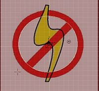
After rendering you will have something like this:
::染后,你会得到这样的东西:
Method 2 - using mesh circle and edges
::方法2 - 使用网状圈和边缘
Instead of using the Bézier Curve, you can use Circles.
::你可以使用圆形.
There are two ways of doing this:
::有两种方法可以做到这一点:
Easy way
::简单的方式
Place two vertices (CTRL+LMB), one on the inner circle and one on the outer circle so that they form a line. This line has to be perpendicular to the circle you are tracing. Then place the cursor on the middle of the circle. Then just use the spin tool under the Mesh tools tab (360 degrees and 32 steps). This creates a circle made of 32 adjacent squares. Give it more steps to increase the quality of the circle.
::放置两个顶点 (CTRL+LMB),一个在内圆上,一个在外圆上,使它们形成一条线.这个线必须垂直于你正在绘制的圆.然后将光标放置在圆的中间.然后只需使用Mesh工具选项卡下的旋转工具 (360度和32步).这就会创建一个由32个相邻的方格组成的圆.为增加圆的质量,给它更多的步骤.
Detailed way
::详细的方式
Go to the top view (NUM7), and press SPACE -> Mesh -> Circle. Accept the 32 vertices, you can make it less but it won't look as good.
::接受32个顶点,你可以减少它,但它看起来不那么好.
Move it into the center of the circle, if you don't then I advise you have wireframe on for the moment (press Z). Then press S, for scale, and make it the correct size for the inside of the circle. Once you have that in the correct place, like so:
::移动到圆的中心,如果不这样做,我建议你暂时启动线框 (按Z).然后按S,缩放,并使其正确的尺寸为圆的内部.一旦你有在正确的地方,这样:
You may need to stretch it sideways a little, then press 'E' to extrude (choose Only Edges), press 'S' to scale and another sized circle will appear, size this appropriately then click LMB.
::您可能需要稍微向侧拉伸,然后按"E"挤出 (选择"仅边缘",按"S"缩放,另一个大小的圆圈将出现,按适当的大小,然后点击LMB.
Deselect the second circle, then select four vertices that are near each other and that form a square.
::取消选择第二个圆,然后选择四个靠近彼此的顶点,
Now press F and a face will appear, i.e. the box will be filled (turn off Wireframe, press z). Now do this right around the circle. To do this, hold down Shift and Ctrl, then draw a circle around the two vertices you wish to deselect with the Left Mouse Button. Then draw a circle around the next two vertices while holding down Ctrl and LMB,
NOT SHIFT
. Shift changes the control from selecting, to deselecting.
::现在按F,将出现一个面,即该框将被填充 (关闭Wireframe,按z).现在在圆周做这件事.这样做,按住Shift和Ctrl,然后用鼠标左键取消选择的两个顶点周围画一个圆.然后按住Ctrl和LMB,而不是SHIFT,在下两个顶点周围画一个圆.Shift将控制从选择,到取消选择.
Once you have gone all around the circle it's time to make the line through the middle. To make the crossing line you need to move 4 of the vertices slightly; example below:
::一旦你绕过了圆圈,那么就需要在圆圈中间做出直线. 要做出交叉线,你需要轻微移动四个顶点; 下面的例子:
Once you do this, highlight the 4 you moved, then press F.
::按下F键, 按下F键,
Making the circle 3D
::让圆形变成3D
Highlight the full circle by pressing A either once or twice. Go to Side View, and press E for extrude and drag it down so that it is the same thickness as the lightning bolt (you'll see why).
::通过按一两次A来突出显示完整的圆圈. 进入侧面视图,按E进行挤出,然后将其拖向下方,使其与闪电螺栓相同厚度 (您将看到为什么).
Now look at what you have made... it looks nice enough but where the lightning bolt goes through the circle it looks a bit odd so we will make it look like the circle is laying on top of the bolt. Where the bolt goes through the circle, note the edges and the vertices. Move them so that the lines are just either side of where the bolt goes through. Then make new edges using CTRL+R on the outsides of these edges. Like so:
::现在看看你做了什么...看起来很好,但是闪电穿过圆的位置看起来有点奇怪,所以我们会让它看起来像圆在螺栓的顶部. 螺栓穿过圆的地方,注意边缘和顶点. 移动它们,使线条只是螺栓穿过的两侧. 然后使用CTRL+R在这些边缘的外面做新的边缘. 就这样:
Now you have squares where the lightning bolt hits the circle. Change to Wireframe (z) if you are not already in it then highlight the 16 vertices of these boxes and raise them. Now do the same for where the center line crosses the bolt but create 4 lines instead of two. To explain why, I've created a diagram.
::现在你有方形,闪电击中圆圈. 换成Wireframe (z) 如果你还没有在其中,然后突出显示这些盒子的16个顶点并提高它们. 现在做同样的,中心线交叉螺栓,但创建4条线而不是两个. 解释为什么,我已经创建了一个图.
Now we can make the finishing touches, add subsurf and set it to 2 or 3 and add color! Then you are done I won't go over subsurf and adding color because people have covered that better than I could in previous 'Noob to Pro' pages. I think that's everything.
::现在我们可以做最后的修改,添加subsurf,设置为2或3并添加颜色! 完成了! 我不会再讨论subsurf和添加颜色,因为人们已经比我在以前的"从新手到专业"页面中更好地涵盖了这一点. 我认为这就是全部.
You should now be looking at something similar to:
::现在你应该看到类似于:
Method 3 - using mesh circle and a cube
::方法3 - 使用网状圈和立方体
Tracing the
No symbol
is somewhat more complex than the lightning bolt. The reason is this symbol is hollow and requires additional planning to trace than just following an outline of an object.
::追踪"不"符号比闪电更复杂.原因是这个符号是空洞的,需要额外的计划来追踪,而不仅仅是遵循一个对象的轮.
I'll be back to explain the difficulties in the near future, so stay tuned.
::我会在不久的将来回来解释这些困难,
One way to do this is outlined below:
::现在我们来看看其中一种方法:
-
The first thing to do is add a mesh circle. Hit
SPACE
and select 'Add -> Mesh -> Circle'. (This circle is mostly for measuring purposes, and will ultimately be removed.)
::首先要做的是添加一个网格圆.点击SPACE,选择'Add -> Mesh -> Circle'. (这个圆主要用于测量目的,最终将被删除.) -
Scale (
SKEY
) and move (
GKEY
) the circle so that it's sides are even with the sides of the logo circle, and the top and bottom are an even distance from the top and bottom of the logo circle. (The logo circle is not perfectly round.)
::缩放 (SKEY) 和移动 (GKEY) 圆,使其边与标志圆的边相等,并且顶部和底部与标志圆的顶部和底部相距均. (标志圆不是完全圆的.)
-
Make sure you're in object mode (
TAB
), add a cube (
SPACE
, 'Add -> Mesh -> Cube') and place it (
GKEY
) on the right edge of the circle so that it is centered on the right edge.
::确保您处于对象模式 (TAB),添加一个立方体 (SPACE, 'Add -> Mesh -> Cube') 并将其 (GKEY) 放置在圆的右边,以便它位于右边的中心. -
Scale (
SKEY
) the cube so that it is the same width as the wall of the circle and touching each side of the wall.
::缩小 (SKEY) 立方体,使其与圆的墙壁宽度相同,并触及墙壁的每一侧. -
Now, we want the 3Dcursor at the center of the logo circle. To do this, go back to object mode (
TAB
), and select the circle that we added earlier (
RMB
), then press
SHIFT+SKEY
and choose 'Cursor -> Selection'. (This is the main reason why we have this circle here.)
::现在,我们希望3D指针位于标志圆的中心. 要做到这一点,回到对象模式 (TAB),并选择我们之前添加的圆 (RMB),然后按 SHIFT+SKEY,选择'Cursor -> Selection'. (这是我们在这里有这个圆的主要原因.) -
Reselect the cube (
RMB
) and
TAB
to edit mode.
::重新选择立方体 (RMB) 和TAB以编辑模式. -
Choose
NUM7
for the top view, and use
RMB
to select only the front face of the cube. (Before this you have to make sure that you are in 'Face select mode'.)
::选择NUM7作为顶部视图,并使用人民币仅选择立方体的前面. (此之前,您必须确保您处于'选择面孔模式'中. -
Press
XKEY
and choose Erase Vertices. This will reduce the cube to a square
::这将减少立方体到一个方形
-
Press
NUM7
to go to the top view then select the Editing panel (
F9
).
::按下NUM7进入顶部视图,然后选择编辑面板 (F9). -
Press
AKEY
to select all, and then make sure that the rotate settings are set to degr:360, Steps:50, Turns: 1. (Actually, Steps can be whatever number suits your fancy. You may want to play with various values.) This is just like we did for creating the man's hat.
::按一下AKEY选择所有,然后确保旋转设置为 degr:360, Steps:50, Turns: 1. (实际上,Step可以是任何适合您的数量.您可能想玩各种值.) 这就像我们为创建男人的帽子所做的那样. -
Click on 'Spin' to extrude the square into a ring.
::点击"旋转"将方形挤出成一个环.
Next we will create the bar.
::接下来我们将创建一个酒吧.
-
Staying in Edit mode, hit
SPACE
and select 'Add -> Cube'. If you haven't moved the cursor since the ring extrusion, it should appear in the middle of the ring.
::如果您在编辑模式下,请按空格,选择'添加 -> 立方体'. 如果您在环挤出后没有移动光标,它应该出现在环的中间. -
Expand (
SKEY
) the cube so that it just encompasses the inside circle of the ring
::扩展 (SKEY) 的立方体,使它只是包含的环的内部圆
-
Scale (
SKEY
) the square in the Y axis (
YKEY
) so that it is approximately the thickness of the logo bar.
::在Y轴 (YKEY) 中缩放 (SKEY) 方形,使其大约与标志条的厚度相同. -
Return to object mode (
TAB
), and rotate (
RKEY
) the ring together with the just designed bar so that it is parallel to the logo bar.
::返回对象模式 (TAB),并将环和刚设计的条一起旋转 (RKEY),使其平行于标志条. -
In Edit Mode (
TAB
), squash the ring in the Y direction (
SKEY
,
YKEY
) so that it fits the logo ring.
::在编辑模式 (TAB) 中,按Y方向 (SKEY,YKEY) 压缩环,使其适合标志环.
-
In edit mode, reselect just the bar. To do this, choose 'Face select mode', and do an area select of the face selectors near the center of the bar (use the
BKEY
, or
SHIFT+RMB
methods).
::在编辑模式下,只重新选择条. 为此,选择'选择面孔模式',并在条的中心附近选择面孔选择器的区域 (使用BKEY或SHIFT+RMB方法). -
Re-rotate (
RKEY
) the bar (in Edit Mode) so that it is parallel to, and in the middle of, the logo bar.
::在编辑模式下,重新旋转 (RKEY) 条,使其平行于标志条,并位于标志条的中间.
-
The next thing we need to do is scale the bar so that it is precisely the same width as the logo bar.
::接下来我们需要做的是调整条的尺寸, -
To do this, choose scale (
SKEY
), and press
YKEY
twice. This will go to local scale mode (local to the object). This is why we were rotating the entire ring, since the ring and bar are part of the same object.
::要做到这一点,选择尺度 (SKEY),然后按YKEY两次. 这将进入本地尺度模式 (本地对象). 这就是为什么我们要旋转整个环,因为环和条是同一对象的一部分.
-
We no longer need the original circle now, (it should be sticking out from the top and bottom of the ring), so select it (
RMB
), and delete it (
XKEY
).
::现在我们不再需要原始的圆圈, (它应该从环的顶部和底部伸出),所以选择它 (RMB),并删除它 (XKEY). -
If you hit
NUM3
You'll see that the bar and the ring are at completely different heights than the lightning bolt. Select and scale them so that they are all roughly the same height (the bar should be slightly higher than the bolt, and the bolt slightly higher than the ring so that all the proper parts are covered.).
::选择和规模,使它们都大致相同的高度 (条应该比螺栓稍高一些,螺栓稍高一些,比戒指,这样所有的适当的部分都被覆盖.). -
You can use the trick above to select (
RMB
) only the bar, scale it in the Z axis (
SKEY
,
ZKEY
) and then hit
SPACE
and choose 'Select -> Inverse' to select the ring (all but the bar).
::您可以使用上面的技巧选择 (RMB) 只有条,在Z轴 (SKEY,ZKEY) 缩放,然后按空格,选择"选择 -> 逆向"选择环 (除了条). -
When done rescaling, press
NUM7
to look at your handiwork.
::按NUM7查看自己的作品.
-
There is one last bit, which is to slightly rotate the whole ring around the X axis so that it is below the top of the bolt and above the bottom.
::需要稍微旋转整个环绕X轴,使其在螺栓顶部下方, -
Once that's done, all that's left to do, is color in the ring.
::一旦完成,剩下的就是在戒指上涂色.