Blender 3D:第四单元:与高级教程起飞
Texture nodes allow you to produce textures that are the result of complex computations. This tutorial will just scratch the surface of what’s possible.
::纹理节点允许你产生由复杂计算产生的纹理. 本教程只是开了可能的表面.
A Simple “Rainbow” Texture
::一种简单的"彩虹"纹理
Start with a new Blender document. Delete the default cube. Add a new plane object. In the Material context in the Object Properties window, click the icon to the left of the material name to assign a material to the plane (there should already be a default unused one called “Material”). In the Texture context, there should already be a texture called “Tex” assigned to this material. Now split the area showing the 3D view into two side-by-side areas. In the right-hand area, bring up the Node Editor. In its area header, you should see a group of 3 little icons next to the menu
![]() ; click on the middle one for Texture Nodes. You will see appear, further along the area header, a popup menu containing the names of the textures so far created in your document: this should be showing the name “Tex” of the texture you assigned to the material for your plane object. And to the right of that, there should be a checkbox titled “Use Nodes”. Check that, and you should see a pair of initial nodes immediately appear in the editor: an
input
node titled “Checker” and an
output
node titled “Output”, with an editable field in it containing “Default”.
; click on the middle one for Texture Nodes. You will see appear, further along the area header, a popup menu containing the names of the textures so far created in your document: this should be showing the name “Tex” of the texture you assigned to the material for your plane object. And to the right of that, there should be a checkbox titled “Use Nodes”. Check that, and you should see a pair of initial nodes immediately appear in the editor: an
input
node titled “Checker” and an
output
node titled “Output”, with an editable field in it containing “Default”.
::开始使用一个新的Blender文档. 删除默认的立方体. 添加一个新的平面对象. 在Object Properties窗口中的Material上下文,点击材料名称的左边的图标来赋予平面的材料 (应该已经有一个默认的未使用的称为Material). 在Texture上下文,应该已经有一个称为Tex的纹理赋予此材料. 现在将显示3D视图的区域分成两个并排的区域. 在右边区域,带出Node Editor. 在它的区域头部,您应该看到一个组3个小图标旁边的菜单; 点击中间一个为Texture Nodes. 您将看到,在区域头部,一个弹出菜单包含文档中迄今为止创建的纹理名称:这应该是
There must be at least one output node in the texture definition; the data fed to this will make up the final texture. The names you assign in the Name field will appear in the Texture context in the Object Properties window, in a popup menu titled “Output:”, with one item for each output node. Initially this may show “Not Specified”: change it to “Default”.
::纹理定义中必须至少有一个输出节点;输入的数据将构成最终的纹理.您在Name字段中赋予的名称将出现在对象属性窗口中的纹理上下文,在弹出菜单中标题为 Output:,每个输出节点有一个项目.最初可能会显示 Not Specified:将其更改为 Default.
|
|
Navigation in the Node Editor:
As in most Blender windows, you can scroll around by dragging with MMB , and zoom the view in and out with the mouse wheel.
|
Each node window has little coloured circles (terminals) on its left and right edges; the ones on the left edge (if any) are inputs for feeding data from other nodes, and the ones on the right edge (if any) are for supplying data to other nodes. Thus, output nodes have no outputs (they’re the final destination for the data), while input nodes have no inputs. Other node types represent intermediate stages in the processing, so they will have both inputs and outputs.
::每个节点窗口在左边和右边都有小的彩色圆圈 (终端);左边 (如果有的话) 是输入来自其他节点的数据,右边 (如果有的话) 是供应给其他节点的数据.因此,输出节点没有输出 (它们是数据的最终目的地),而输入节点没有输入.其他节点类型代表处理中的中间阶段,因此它们将有输入和输出.
Back in the Node Editor, click on the titlebar of the “Checker” node window and use either X or DEL to delete it. Note that, unlike deleting objects in the 3D view, there is
no
confirmation popup: the node immediately disappears. (Of course, you can use CTRL + Z to undo operations in the usual way.)
::回到节点编辑器,点击"检查器"节点窗口的标题,然后使用X或DEL删除它.请注意,与3D视图中删除对象不同,没有确认弹出窗口:节点立即消失. (当然,您可以使用CTRL + Z以通常的方式撤销操作.)
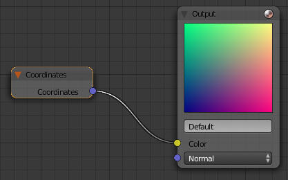
Now go to the “Add” menu (or use the usual SHIFT + A shortcut), find the “Input” submenu, and select the “Coordinates” item. This will add a new input node, which just produces the unadorned texture coordinates as its data. The newly-added node will follow the mouse around; press LMB once you have moved it to a convenient place. You will see the new node has one output terminal, titled “Coordinates”. Left-click on this, and drag to the input terminal in the Output window with the word “Color” and a small rectangular colour swatch next to it. Voilà! A line (effectively a wire) should appear connecting the two terminals, and you should see the big square colour swatch in the Output window change from black to a whole rainbow of colours. That’s your texture!
::现在进入"添加"菜单 (或使用常用的"转换+A"快捷键),找到"输入"子菜单,选择"坐标"项. 这将添加一个新的输入节点,它只会生成无花纹的纹理坐标作为其数据. 新添加的节点将随着鼠标转动;一旦你将其移到一个方便的地方,按下LMB. 你会看到新的节点有一个输出终端,标题为"坐标". 左键点击它,并拖到输出窗口中的输入终端,上面写着"颜色"字和旁边一个小的矩形颜色标签. Voilà! 应该出现连接两个终端的线 (实际上是一个线),你应该看到输出窗口中的大方形颜色标签从黑色变为整个彩虹的
If you make a wrong connection, you can move or cut it by dragging the output end of the wire away from the input terminal it is attached to with LMB , to either a new input terminal or simply into an unoccupied space between nodes; when you let go the button, the wire will attach to the new input terminal in the former case, or disappear in the latter case.
::如果您连接错误,您可以通过将线的输出端拖离它与LMB连接的输入终端,将其移动或切断到新的输入终端或简单地进入节点之间的空白空间;当您放开按时,线将在前一种情况下连接到新的输入终端,或者在后一种情况下消失.
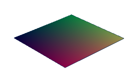
At this point, you should be able to hit F12 to render, and you will see your plane object with the rainbow texture applied. You can see why I chose a Plane object: being flat, the entire texture is visible from one camera angle.
::现在,你应该可以按F12进行染,你会看到你的平面对象,上面有彩虹纹理.你可以看出我为什么选择平面对象:平面,整个纹理从一个摄像头角度可见.
Scalars Versus Vectors
::标量对向量
The wires carry numbers between nodes. These numbers can be of two kinds: a
scalar
is a single real quantity, like “0.5”, while a
vector
can consist of two, three or four scalars in a sequence, like “(0.5, 0.75, 0.2, 1.0)”. The number of components in a vector is also known as the
dimension
of the vector. Two-dimensional vectors can be used to represent texture coordinates, while three-dimensional vectors can represent positions in space. Colours can be represented with 3 dimensions (R, G,B or H, S, V) or 4 dimensions (RGB or HSV plus alpha channel).
::线在节点之间携带数字.这些数字可以有两种:一个标量是一个单一的实数,如0.5,而一个向量可以由两个,三个或四个标量组成,如0.5,0.75,0.2,1.0) .向量的组件数也被称为向量的维度.二维向量可以用来表示纹理坐标,而三维向量可以表示空间中的位置.颜色可以用3维 (R,G,B或H,S,V) 或4维 (RGB或HSV加上α频道) 来表示.
Some nodes operate on scalars, while others operate on vectors. And there are nodes where some terminals input or output scalars, while others input or output vectors.
::有些节点在标量级上运行,而另一些则在向量级上运行. 还有节点,有些终端输入或输出标量级,而另一些则输入或输出向量级.
Try this. To the above Coordinates and Output nodes, add a “Separate RGBA” node (under the “Color” submenu of the “Add” menu). Feed the output from the Coordinates node to the “Color” input node of the Separate node. Now connect just the “Red” output terminal from the Separate node to the output node (if you move the newly-created node on top of the existing wire, this should happen automatically):
::尝试这样做. 在上面的坐标和输出节点中,添加一个"Separate RGBA"节点 (在"Add"菜单的"Color"子菜单下). 将坐标节点的输出输入到"Separate"节点的"Color"输入节点. 现在将"Red"输出终端从"Separate"节点连接到输出节点 (如果您将新创建的节点移动到现有线的顶部,这应该自动发生):
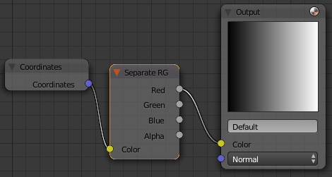
See how the Output swatch shows just a greyscale ramp running from black on the left to white on the right? This shows how the first dimension of a vector is interpreted as the red component in an RGB colour, but as the X coordinate in a position. Remove the output from the Red terminal (delete the existing wire), and take it from the Green terminal instead (by dragging a new wire from Green to the Color terminal on the Output node); now you will see the ramp going from black at the bottom to white at the top. The second dimension of a vector is the green component in an RGB colour, and the Y coordinate in a position.
::输出样本显示的只是一个从左边的黑色到右边的白色的灰度坡道. 这显示了向量的第一个维度是如何被解释为RGB颜色中的红色组件,但作为X坐标. 从红色终端移除输出 (删除现有线),并从绿色终端取出 (通过将一个新的线从绿色拖到输出节点上的颜色终端); 现在你会看到坡道从底部的黑色到顶部的白色. 矢量的第二个维度是RGB颜色中的绿色组件,和Y坐标在一个位置.
The terminals have different colours to remind you what type of data they
should
be used for (purplish for coordinates, yellow for colours, grey for scalars), but
as far as Blender’s Node Editor is concerned, colours and positions are not actually different types.
Both are vectors, and one can be interpreted as the other. This can be (ab)used for some creative effects! For example, the name of the “Separate RGBA” node says it’s for separating an RGBA colour into its components, but here we are using it to take apart a coordinate vector instead.
::终端有不同的颜色提醒你它们应该用于什么类型的数据 (坐标为紫色,颜色为黄色,标量为灰色),但就Blender的节点编辑器而言,颜色和位置实际上不是不同的类型. 两者都是向量,一个可以被解释为另一个. 这可以 (滥用) 进行一些创意效果! 例如, Separate RGBA节点的名字说它用于将RGBA颜色分成其组件,但在这里我们使用它来拆分一个坐标向量.
Note also in the above, that the Color terminal on the Output node expects a vector RGB colour, but when you feed it a single colour component (i.e. a scalar), it simply replicates it the necessary number of times to make a vector of the required dimension. Since all components of the RGB colour are the same, you get a shade of grey.
::在上述内容中还需要注意的是,输出节点上的颜色终端预计向量RGB颜色,但是当你给它一个单一的颜色组件 (即一个标量),它只需要复制它所需的次数来制造一个所需维度的向量.由于RGB颜色的所有组件都相同,你得到一个灰色的阴影.