Blender 3D:第四单元:与高级教程起飞
Material nodes look very similar to texture nodes, and indeed there is a fair amount of overlap in functionality. Some important differences are:
::材料节点看起来与纹理节点非常相似,而且在功能方面确实存在相当多的重叠.一些重要的区别是:
-
Functions for performing spatial transformations (e.g. rotation and scaling) are only available for texture nodes.
::执行空间转换 (例如旋转和缩放) 的功能仅适用于纹理节点. -
Functions for altering diffuse versus specular colours and rendering parameters, like translucency, are only available for material nodes.
::仅可用于材料节点的功能是改变扩散与反射颜色和染参数,如半透明度.
A Simple Graduated Material
::一种简单的渐进式材料
First of all, let’s set up a really basic modelling scene to show off the node-based material you’ll be creating in a moment.
::首先,让我们设置一个非常基本的建模场景, 以展示你在一会儿将要创建的基于节点的材料.
Open a new Blender document, with the default cube, default light and default camera. Create a plane object. Rotate and position that so it lies behind the cube from the camera’s viewpoint. Scale the plane up to say, 4x, to form a decent-sized backdrop. Assign it a new default material, and a texture with some detail to it; I used a simple Marble with default settings, except under the “Map To” miniwindow I changed the colour to a medium grey from the default magenta, to stop it hurting my eyes.
::打开一个新的Blender文档,使用默认的立方体,默认的光和默认的摄像头.创建一个平面对象.旋转并将其定位,以便从摄像头的角度看立方体后面.将平面缩放到4倍,以形成一个体面的大小的背景.赋予它一个新的默认材料,并对其进行一些细节的纹理;我使用了一个简单的Marble,默认设置,除了在Map To小窗口下,我将颜色从默认的红色改为中灰色,以防止它伤害我的眼睛.
Now select the cube. Scale it 3x in the Z-axis; the elongated proportions should show off a gradation more nicely. In the “Material” miniwindow, set the “Col” (diffuse) colour to white, and the alpha to zero. In the “Mirror Trans” miniwindow, turn on “Ray Transp” and set the “IOR” to some suitable refractive index, say 1.5 for glass.
::现在选择立方体. 在Z轴上缩放3倍; 长长的比例应该更好地显示分级. 在"材料"小窗口中,将"色" (扩散) 颜色设置为白色,而"α"为零. 在"镜像转换"小窗口中,打开"光线转换"并将"IOR"设置为合适的折射率,例如玻璃1.5.
Hit
F12
to do an initial render, just to confirm you’ve got everything nicely arranged.
::按F12进行初始染, 只是为了确认你已经把一切安排好了.
With the cube still selected, open the Node Editor. By default, the Material Nodes mode should already be selected, and the combo box should be showing the name of the material you assigned to the cube; select it if it’s not. Click the “Use Nodes” button, and immediately two node windows should appear, a Material one and Output one.
::仍然选择立方体,打开节点编辑器.默认情况下,应该已经选择了材料节点模式,组合框应该显示你分配给立方体的材料名称;如果没有,请选择它.点击"使用节点"按,立即会出现两个节点窗口,一个是材料窗口和一个是输出窗口.
Click on the title of the Material node window, and use
XKEY
or
DEL
to get rid of it. Go to the “Add” menu, “Input” submenu, and add a new “Geometry” node. Also add a new “Extended Material” node. And from the “Convertor” submenu, a new “Separate RGB” node. In the middle of the Extended Material node window, there is a popup menu showing you the names of the materials in your document; select name of the material you previously assigned to the cube again.
::点击材料节点窗口的标题,并使用XKEY或DEL来删除它.进入"添加"菜单,"输入"子菜单,并添加一个新的"几何"节点.还添加一个新的"扩展材料"节点.从"转换器"子菜单,一个新的"分离RGB"节点.在扩展材料节点窗口的中间,有一个弹出菜单显示您的文档中的材料名称;再次选择您之前分配给立方体的材料名称.
Make sure there are no wires running between any of the nodes; now run one from the “Color” output terminal on the Material node to the “Color” input on the Output node, and one from the “Alpha” output on the former to the “Alpha” input on the latter.
::确保任何节点之间没有线路运行;现在运行一个从材料节点上的"颜色"输出终端到输出节点上的"颜色"输入,一个从前一个节点上的"Alpha"输出到后一个节点上的"Alpha"输入.
Notice that, next to each of the input terminals in the Material window, there is either a field for entering a scalar value (grey terminals), or a button which pops up a little set of controls for letting you specify X, Y and Z components for a vector (blue terminals), or a colour swatch which pops up to let you pick a new colour (yellow terminals). This way, you don’t have to make connections to all the inputs, or indeed any of them; any unconnected inputs will be set to the constant value that you specify.
::值得注意的是,在材料窗口中的每个输入端子旁边,要么有输入标量值的字段 (灰色端子),要么有一个按,它会弹出一组控制,让你指定X,Y和Z组件用于向量 (蓝色端子),或者一个颜色样本,它会弹出,让你选择一个新的颜色 (黄色端子).这样,你不必连接所有输入,甚至是其中任何一个;任何未连接的输入都将被设置为你指定的常数值.
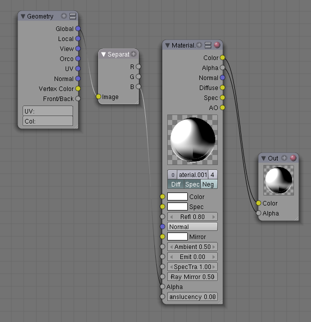
Anyway. connect a wire from the “Global” output of the Geometry node to the “Image” input of the Separate RGB node. “But geometry isn’t a colour!?” I hear you cry. But as explained on
Texture Nodes
, a vector is a vector. Feeding in a position instead of a colour to Separate RGB means its outputs are not the R, G and B components of the colour, but the X, Y and Z components of the position. So run another wire from the B (i.e. Z) output of Separate RGB to the Alpha input of the Extended Material window. The resulting layout should look like this:
::无论如何,将几何节点的"全球"输出线连接到"独立RGB节点的"图像"输入线. "但几何不是颜色吗?" 我听到你哭泣. 但正如在"纹理节点"中解释的那样,矢量是矢量. 将颜色输入到"独立RGB"的位置意味着它的输出不是颜色的R,G和B组件,而是位置的X,Y和Z组件. 因此,从独立RGB的B (即Z) 输出线运行到扩展材料的Alpha输入. 结果的窗口布局应该是这样的:
Now you’re ready to render. But before hitting
F12
, hit
JKEY
to switch render buffers. That way you still have the previous render to compare with. Once the render window comes up, you can hit
JKEY
to alternate between the two renders.
::现在您准备染. 但在击F12之前,请点击JKEY来切换染缓冲区. 这样您仍然可以使用前一个染来进行比较. 一旦染窗口出现,您可以点击JKEY来在两个染器之间交替.
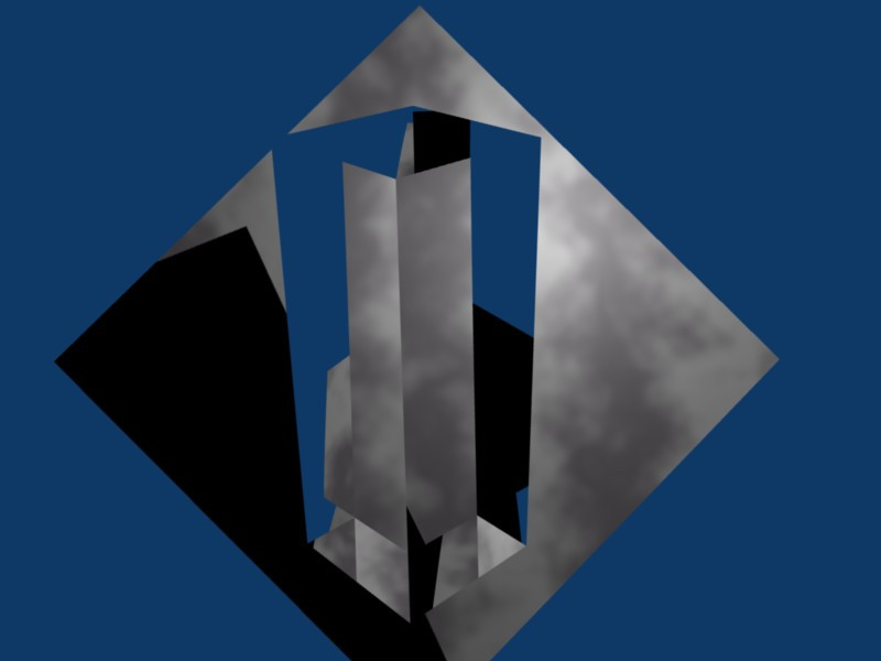
Here’s what my node example looked like (note I turned the energy of the lamp down to 0.5, otherwise it seemed too bright):
::这就是我的节点示例 (注意我把灯的能量降低到0.5,否则它看起来太亮):
Notice the gradation of transparency along the Z-axis, from fully transparent at the bottom to fully opaque at the top.
::沿着Z轴的透明度的分级, 从底部完全透明到顶部完全不透明.
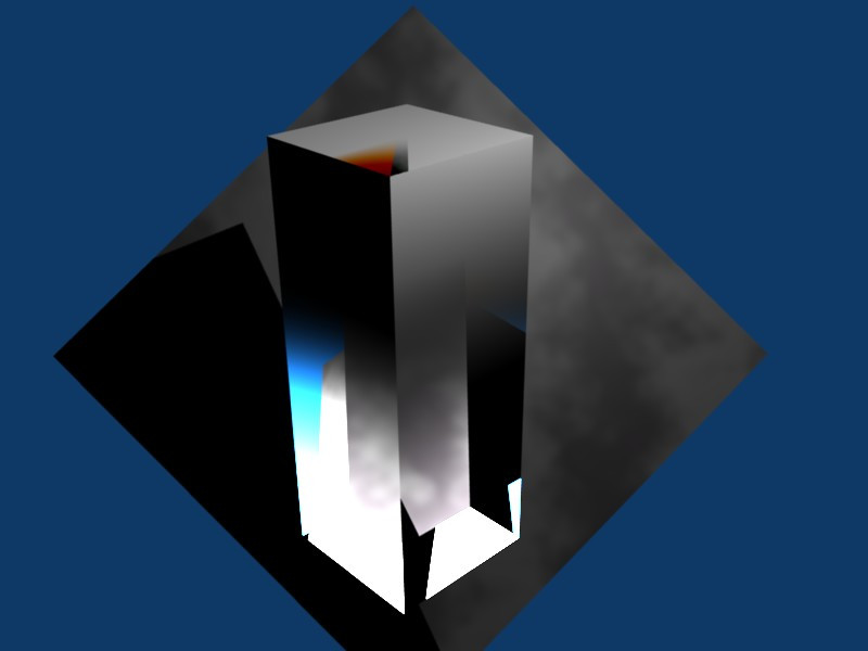
For added fun, try taking the material Alpha setting from the R or G outputs of the Separate RGB node instead, just to see the gradation orient along the X or Y axes.
::为了增加乐趣,尝试从R或G输出中取材质Alpha设置 单独的RGB节点,只是为了看到沿X或Y轴的分级方向.