Blender 3D:各种各样的教程
章节大纲
-
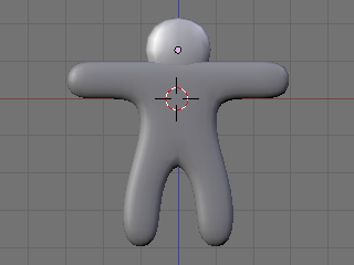
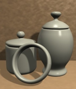
In this tutorial you will learn how to make a simple gingerbread man. In a later tutorial you will be able to make an animation with this gingerbread man.
::在本教程中,你将学习如何制作一个简单的饼人. 在后面的教程中,你将能够制作一个动画与这个饼人.In this tutorial we will tie together everything we've talked about up to this point, including extruding, subdividing and rendering, and throw in basic lighting.
::在本教程中,我们将把我们到目前为止所讨论的一切联系在一起,包括挤出,分类和染,并加入基本的照明.Modeling
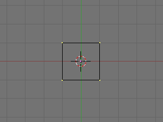
::模拟First, start Blender. You should see the usual top view of a cube in the 3D window, surrounded by a grid 'floor'.
::首先启动Blender. 在3D窗口中,你应该看到平常的立方体顶部图, 周围是网格"地板".- Review— Zoom in or out with SCROLL or CTRL+MMB . Pan with SHIFT+SCROLL and CTRL+SCROLL . Make sure you are in orthographic view. Press NUM5 to toggle between orthographic view and perspective view. You can tell you're looking at an orthographic view while looking down from the top ( NUM7 ) of the cube: wherever you pan the window, you never see any part of the cube except the top.
-
Display editing controls in the buttons window by clicking on the Editing context button
 or by pressing
F9
.
or by pressing
F9
.
::在按窗口中显示编辑控件, 单击编辑上下文按或按F9.
Adding Vertices
::增加顶点-
Select the cube by clicking
RMB
on it. (It may already be selected.) Remember, selected objects are outlined in pink.
::选择立方体,点击人民币. (可能已经选择了.) 请记住,选择的对象是粉红色的. -
Switch from object mode to edit mode by pressing
TAB
, which toggles between object and edit modes. In edit mode, at first, you'll see colored dots at the vertices of the cube. Selected vertices are highlighted in yellow. Unselected vertices are pink. (You'll see the dots when editing in vertex select mode. In edge select or face select mode, you'll see colored edges and faces instead.)
::通过按下TAB,从对象模式切换到编辑模式.在编辑模式中,首先,您将在立方体的顶点看到彩色点.选定的顶点以黄色亮点.未选的顶点是粉红色的. (在顶点选择模式中编辑时,您将看到点.在边缘选择或面部选择模式中,您将看到彩色边缘和面部.) -
Select all vertices of the cube. Press
AKEY
once. If the vertices are yellow, you've selected all of them. If they are pink, you've deselected all of them. If necessary, press
AKEY
again so that all vertices are selected/yellow.
::选择立方体的所有顶点. 按一下 AKEY. 如果顶点是黄色的,则您已经选择了它们. 如果它们是粉红色的,则您已经取消了它们的所有选择. 如果需要,请再次按 AKEY,以便所有顶点被选择/黄色.
-
Subdivide the faces of the cube, using any of the following methods. (All vertices of the cube should still be selected.)
-
Click the Subdivide button in the Mesh Tools panel in the buttons window.
::在按窗口的网格工具面板中点击分为组的按. -
With the mouse pointer in the 3D window –
-
Press
WKEY
to display the Specials menu, then choose Subdivide.
::按WKEY显示"特殊菜单",然后选择"分类". -
Press
SPACE
to display the toolbox, then choose Edit → Edges → Subdivide.
::按空格显示工具箱,然后选择编辑 → 边缘 → 分区.
::在3D窗口中按鼠标指针按WKEY显示"特殊"菜单,然后选择"分区".按SPACE显示"工具箱",然后选择"编辑" →"边缘" →"分区". -
Press
WKEY
to display the Specials menu, then choose Subdivide.
-
Click the 3D window's Mesh menu, and choose Edges → Subdivide.
::单击3D窗口的"网格"菜单,然后选择"边缘" → "分区".
::使用以下方法中的任何一种,将立方体的面部划分. (立方体的所有顶点仍然应被选择.) 在按窗口的网格工具面板中,单击"划分"按. 在3D窗口中,使用鼠标指针按WKEY显示"特殊"菜单,然后选择"划分".按SPACE显示"工具箱,然后选择"编辑" →"边缘" →"划分".单击3D窗口的"网格"菜单,然后选择"边缘" →"划分".按"分"按,然后选择"边缘" →"划分".按"分"按,然后选择"边缘" →"划分".按"分"按,然后选择"分"按,然后选择"分"按. -
Click the Subdivide button in the Mesh Tools panel in the buttons window.
-
Your cube now has more vertices.
Subdividing
edges adds vertices so you can create more complex shapes.
::立方体现在有更多的顶点. 边缘的分化增加了顶点,

Selecting a Subset of Vertices
::选择一个顶点子集We'll select six vertices on the upper half of one side of our cube, where we'll extrude an arm.
::我们将在立方体的一侧上半部分选择六个顶点,-
Deselect all vertices by pressing
AKEY
.
::通过按键删除所有顶点. -
View the cube from the front (
NUM1
).
::从前方 (NUM1) 看到立方体. -
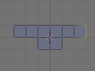
Select the six vertices on the top half of the left side of the cube (see below) using one of the following methods.
-
Press
BKEY
and drag a rectangle around the top left and middle left vertices (viewing from the front).
::按下 BKEY 键,然后在左上和中间的左顶点 (从前方看) 周围拖动一个矩形. -
Press
CKEY
to see a circle around your mouse pointer.
SCROLL
to change the size of the circle. Position the circle around the top left and middle left vertices, together or one at a time, and click
LMB
. Click
RMB
to finish.
::按CKEY以看到鼠标指针周围的圆. 滚动以更改圆的尺寸. 将圆放在左上和中间的左顶点周围,同时或一次一个,然后单击LMB. 单击RMB完成.
::使用以下方法之一选择立方体左侧上半部分的六个顶点 (见下文).按下 BKEY,在左上和中间的左顶点 (从前方查看) 周围拖动一个矩形.按下 CKEY,在鼠标指针周围看到一个圆.SCROLL 改变圆的尺寸.将圆放在左上和中间的左顶点周围,一起或一次,然后单击 LMB.单击 RMB 完成. -
Press
BKEY
and drag a rectangle around the top left and middle left vertices (viewing from the front).
-
Take a closer look at the selected vertices by viewing the model from a different angle (drag with
MMB
).
::通过从不同的角度观察模型 (使用MMB拖动) 来更仔细地观察所选的顶点. -
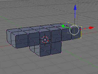
If you find that you have only selected two vertices and not six, make sure the "Occlude Background Geometry" button is off. That button is the right-most of the selection mode buttons, below. (It's called "Limit selection to visible" in Blender 2.45 and earlier. It doesn't appear if Blender is drawing in wireframe style.) Try selecting the vertices again.
::如果您发现您只选择了两个顶点而不是六个,请确保"遮住背景几何"按已关闭.该按是下面的选择模式按中最右边的. (在Blender 2.45及更早版本中称为"将选择限制在可见的位置".如果Blender在使用线框图形时,它不会显示).请再次尝试选择顶点.
-
If you still selected just two vertices, change to a wireframe drawing by pressing
ZKEY
, which toggles between wireframe and solid drawing types. Try selecting again.
::如果您仍然只选择了两个顶点,请按ZKEY,切换到线框图,该键可以在线框和实体图类型之间切换. 尝试再次选择. -
Yet another way to select the six vertices is to select the two faces they define. Click the Face Select button from the selection mode buttons (above), or press
CTRL+TAB
to display a Select Mode menu and choose Faces. Rotate the cube to view the left side and click
RMB
in the center of one of the two upper faces. Hold
SHIFT
and click
RMB
in the center of the other upper face.
::另一个选择六个顶点的方法是选择它们定义的两个面.点击选择模式按中的面选择按 (上),或按Ctrl+Tab显示选择模式菜单并选择面.旋转立方体以查看左侧,在两个上面中的一个的中间点击人民币.按住SHIFT,在另一顶面的中间点击人民币.
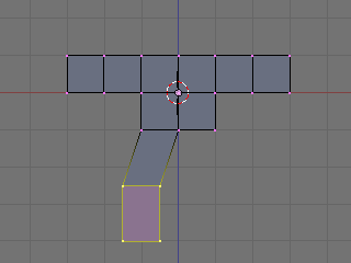
Extruding Arms
::挤出臂-
View from the front by pressing
NUM1
.
::从前方看,按下NUM1. -
Extrude the selected vertices/faces by pressing
EKEY
to display an Extrude menu, then choosing Region. Hold
CTRL
to snap your position to the grid, then move your mouse left to put the new vertices on the adjacent gray line of the grid one unit to the left. Click
LMB
.
::通过按 EKEY 显示一个 挤出菜单,然后选择区域. 按住 CTRL 将您的位置快速移到网格中,然后将鼠标移到左边,将新顶点放在左边一单位的网格的邻近灰色线上. 点击 LMB. -
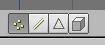
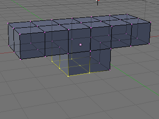
Repeat so that your model looks like below (from front view,
NUM1
).
::重复这样做,使你的模型看起来像下面 (从前方,NUM1).
-
Deselect all vertices/faces with
AKEY
.
::使用AKEY取消所有顶点/面. -
Perform the same extrusion on the right side of the cube, selecting six vertices and extruding twice as explained above.
::在立方体的右侧进行相同的挤出,选择六个顶点并按上述说明进行两次挤出. -
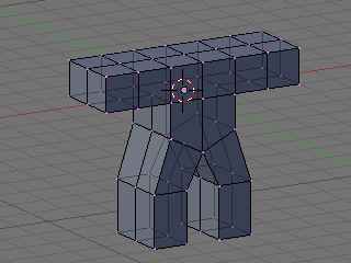
The gingerbread man's arms are in place, as in the illustrations below.
::饼男的手臂已经摆在位,

Extruding Legs
::挤出脚-
Make sure all vertices are unselected, using
AKEY
once or twice.
::确保所有顶点都没有被选中,使用AKEY一次或两次. -
View from the front (
NUM1
).
::从前方的景观 (NUM1). -
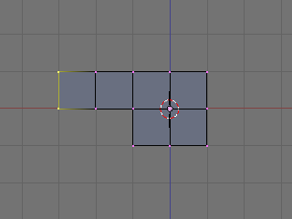
Select the six vertices on the left half of the cube's bottom. Extrude them downward to a point in between the first and second heavier gray lines beneath the cube. (The gray lines in the grid represent Blender units.) Holding down
CTRL
, the extruded region may snap to the heavier gray lines—hold down
CTRL+SHIFT
and the region will snap to tenths of Blender units. Click
LMB
to finish.
::选择立方体底部左半部分的六个顶点.将它们向下挤压到立方体下面的第一和第二个较重的灰色线之间的点. (网格中的灰色线代表了混合器单位.) 按住Ctrl,挤压区域可能会快速到较重的灰色线按住Ctrl+SHIFT,该区域将快速到混合器单位的十分之一. 点击LMB完成. -
An alternative to positioning the extrusion with the mouse is simply typing the distance. Enter 1.5 to extrude 1 1/2 units out. On a Mac, enter the number 1, press fn with the key that is right under
LKEY
and
MKEY
on Azerty (the one with /:,), and press the number 5.
::选择鼠标排挤位置,只需输入距离.输入1.5以挤出1 1/2单位.在Mac上,输入数字1,按下Azerty上LKEY和MKEY下方的键 (带有/:的键),然后按下数字5.
-
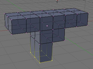
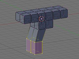
Extrude the same region again, to the third gray line (1.5 again). It should look like this:
::再一次挤出同一个区域,到第三条灰色线 (1.5 再次).应该看起来像这样:
-
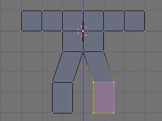
Shift the lower leg to the outside as follows.
-
Select the bottom 12 vertices of the leg (which look like 4 from front view), using
BKEY
.
::使用BKEY选择脚的下面12个顶点 (从前方看起来像4个). -
Grab the selection with
GKEY
. Press
XKEY
to limit movement to the x axis. Move the vertices to the left by half a square, holding
CTRL
or
CTRL+SHIFT
to snap to the grid, and click
LMB
.
::使用GKEY抓取选项.按XKEY限制移动到x轴.将顶点移动到左边半个方形,按住CTRL或CTRL+SHIFT将其快速移到网格,然后点击LMB.
::按下面的方法将下腿部向外移动.使用BKEY选择下12个腿部顶点 (从前方看起来像4个).用GKEY抓取选择.按XKEY限制运动到x轴.将顶点向左移动半个方形,按住CTRL或CTRL+SHIFT将其快速移到网格,然后点击LMB. -
Select the bottom 12 vertices of the leg (which look like 4 from front view), using
BKEY
.
-
Create a second leg on the right side, in the same fashion.
::在右侧创建第二条腿,以同样的方式.
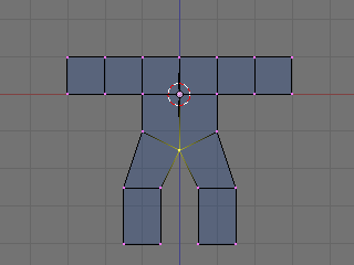
Dropping the Groin
::让下腰部的部位下降Lengthen the groin (where the two legs join):
::延长部 (两条腿相交的地方):-
Deselect all vertices by pressing
AKEY
.
::通过按键删除所有顶点. -
Select the 3 vertices at the groin (which look like 1 from front view), using
BKEY
.
::使用BKEY选择沟上的3个顶点 (从前方看起来像1个). -
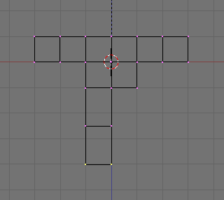
Grab the vertices by pressing
GKEY
. Press
ZKEY
to limit movement to the z axis. Move the vertices down 1/2 of a square, or type -0.5 to specify the distance. (Older versions of Blender require
NKEY
before typing -0.5.)
::通过按 GKEY 抓取顶点.按 ZKEY 将移动限制在 z 轴上.将顶点移动到正方形的1/2,或输入 -0.5 来指定距离. (旧版本的 Blender 需要 NKEY 才能输入 -0.5.)
Adding a Head
::增加一个头部-
Switch the 3D window from Edit mode back to Object mode by pressing
TAB
.
::通过按TAB将3D窗口从编辑模式转换回对象模式.
Noob Note: I found it easier to remain in edit mode while creating the cube as this makes the cube part of the original mesh. This allows you to add the subsurf to all parts at once.
::创建立方体时保持编辑模式更容易,因为这使立方体成为原始网格的一部分. 这允许您一次性添加子表面到所有部分.-
Click
RMB
on the object to select it then press
SHIFT + SKEY
and select
Cursor → Selection
. This will make sure the cube you'll add next will be near where you want it.
::按一下 RMB 选择该对象,然后按 SHIFT + SKEY,选择 Cursor → Selection. 这样可以确保您接下来添加的立方体将接近您想要的位置.
-
Press
SPACE
and put your mouse on the mesh option and select cube. In others versions, you can also hit
SPACE
and , in the menu that comes up, choose
Add → Mesh → Cube
.
::在其他版本中,您还可以按空间,并在出现的菜单中选择添加 → 网格 → 立方体.
-
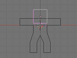
Press
GKEY
and put your new cube about 1/3 of the way down the neck (to achieve this, you can press
GKEY
and
ZKEY
: enter 1.33).
::按下GKEY,然后把你的新立方体放到子的1/3左右 (为了实现这一点,你可以按下GKEY和ZKEY:输入1.33).
Now we will make it look more like a ginger bread man by making it thinner.
::现在我们将使它看起来更像是生面包的人,-
Select all with
AKEY
.
::使用AKEY选择所有.
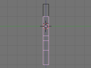
-
Go to side view with
NUM3
.
::通过NUM3进行侧视.
-
Press
SKEY
for scale and press
YKEY
for Y-axis and then move your mouse to the middle until it is about 0.3 (use
CTRL
for fixed values).
::按下 SKEY 按下尺度,按下 YKEY 按下 Y 轴,然后将鼠标移到中间,直到它大约为 0.3 (使用 CTRL 确定值).
-
Remember X-axis is the Red arrow/line, Y-axis is the Green one, and Z-axis is Blue (like RGB video mode).
::记住X轴是红色的箭头/线,Y轴是绿色的,Z轴是蓝色的 (就像RGB视频模式).
-
Use the
MMB
to spin the view around and examine your handiwork.
::通过MMB, 转动视图, 检查自己的作品.
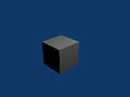
At this point, it doesn't look entirely like a gingerbread man, does it? It's a bit too ... chunky. For the last bit, we'll smooth it out.
::现在看起来不像饼人, 太粗了.-
Make sure you've selected the body in object mode.
::确保您已选择"物体模式"的身体.
-
Select the editing panel in the buttons window (or hit
F9
).
::在按窗口中选择编辑面板 (或按F9).
-
In the Modifiers tab, Add a "Subsurf" modifier.
::在修改器选项卡中,添加一个"潜水"修改器.
-
Set the level of the subdivisions to 2, and the number of render levels to 3.
::设置分区的级别为2,染级别的数量为3.
Noob question: When I add the cube for the head, it stops me from being able to edit the body - it will only select the head to apply subsurf to, even if the body looks like it's selected!
::只有选择头部才能应用subsurf, 即使身体看起来已经被选择了!Answer: When you created the cube you made a second object. To select a different object, press tab to enter Object mode. Select the body. Then enter edit mode again if you want to edit the body.
::答案:当你创建立方体时,你创建了一个第二个对象. 要选择一个不同的对象,按标签进入对象模式. 选择体. 然后再次进入编辑模式,如果您想编辑体.-
You can press the
ZKEY
to switch back and forth between wire-frame view and solid view.
::您可以按下ZKEY键来在线框视图和实体视图之间来回切换.
-
(Noob Note: Easiest way to really get a feel for what is going on in the 3d world is to split into four screens and setting each one to
NUM7
,
NUM3
,
NUM1
, and
NUM0
to see all angles and what it will look like at render.)
::让我们看看它在染时的样子. 现在我们可以看到它在染时的样子.
Noob Question: How?
::如何做到?Answer: To split an area move the cursor to an area between two current areas (e.g. between the 3D view and the buttons), when you see the double ended arrow (used to move the divide) click RMB and select Split Area , you will then see a line appear dividing the area in two. Move this to where you want the divide and click LMB.
::答:要将一个区域分成两部分,请将光标移到两个当前区域之间的区域 (例如3D视图和按之间),当您看到双端箭头 (用于移动分区) 时,请单击人民币并选择分区,然后您将看到一条线将区域分成两部分. 将其移到您想要分区的地方,然后单击LMB.-
In the 'Link and Materials' section, select 'Set Smooth'.
::在"链接和材料"部分,选择"设置光滑".
Noob question: Where? Assuming this refers to the 'Materials' section on the 'Properties' window, there is no 'Smooth' setting.
::假设这指的是"属性"窗口的"材料"部分, 没有"光滑"设置.(Note that here I had the same problem as before, with superposed vertices. Select all vertices, then press WKEY and select Remove Doubles to clean your model. You will see that it will look much better after removing the extra vertices with Remove Doubles)
:请注意,我在这里遇到的问题与之前相同,与叠加的顶点.选择所有顶点,然后按WKEY,选择删除双重来清除你的模型.你会看到它将看起来更好了,删除额外的顶点与删除双重)
-
Press the
ZKEY
to return to wire-frame view.
::按下ZKEY以返回线框视图.
-
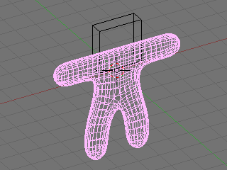
Now repeat the process above to smooth the head.
::现在重复上述过程,
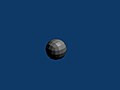
Looks a lot more like a gingerbread man now, doesn't it?
::现在看起来更像是个饼人,不是吗?Camera Positioning and Rendering
::摄像头定位和染This guide will show you how to intuitively get the best frame of your 3D scene with no effort!
::这本指南将告诉你如何直观地获得最好的 3D 场景的,-
Press
TAB
for Object view mode.
::按TAB以进入对象视图模式. -
Press
NUM0
to get the Camera View.
::按NUM0以获得摄像头视图. -
Select the camera by clicking
RMB
on the outermost rectangle.
::选择相机,点击最外的矩形上的人民币. -
Press
GKEY
and move your mouse to adjust the position of the camera (
XKEY
,
YKEY
,
ZKEY
and
CTRL
may be useful here).
::按下GKEY,然后移动鼠标来调整相机的位置 (XKEY,YKEY,ZKEY和CTRL在这里可能很有用). -
In addition, you can press
NUM7
to get the Top View and press
RKEY
to rotate the camera to the best angle.
::按下RKEY将摄像机旋转到最佳角度. -
After you are happy with the position, press
F12
to render it.
::按F12进行染.
If your render comes out a little dark, try moving the lamp closer to the gingerbread man.
::如果你的染效果有点暗,Noob note: Another way to move around the camera is pressing SHIFT + FKEY after pressing NUM0 to enter Fly mode. The keys for fly mode appear in the header of the 3D view pane.
::其他方法是按下SHIFT+FKEY,然后按下NUM0进入飞行模式.飞行模式的键出现在3D视图面板的头部.Noob note: Ctrl+Alt+NUM0 "teleports" the camera to your 3d view.
::让我们来看看它.
Noob Note: By pressing X, Y or Z twice you will use a local base of the space, with those it's much easier. For example if you are facing the Z axis from 45 degrees, and you want to go left 1 unit, using the global base, you will have to go 1.72 (around sqrt(2)) along X and the same along Y, instead moving by 1 in the local frame of reference.
::笔记:按 X,Y 或 Z 两次,你将使用空间的局部基点,用这些更容易.例如,如果你面对 45 度的 Z 轴,你想向左移动 1 个单位,使用全局基点,你将不得不沿 X 移动 1.72 (约 sqrt ((2)) 和沿 Y 移动 1,而不是在局部参考框架中移动 1.Applying Textures
::应用纹理
This builds on the previous guide: Modeling a Volcano .
Note: It seems that textures can only be applied to one object at a time, so this must be done twice (i.e. The head and body are two separate objects.) The settings that were chosen can successfully be applied to each object for a consistent result. Some settings can not be applied equally for consistent results.
::这是在前面的指南: 建模火山. 注意: 似乎纹理只能一次应用于一个对象,所以必须两次 (即头部和身体是两个独立的对象). 选择的设置可以成功地应用于每个对象以获得一致的结果. 有些设置不能同等地应用于一致的结果.N00b Note: if you join the 2 objects before applying the textures you do not have to do the process 2 times, just select the 2 objects, CTRL+J and the accept
::需要在应用纹理之前连接两个对象, 您不需要重复这个过程, 只需选择两个对象, CTRL+J 和接受-
In "Object Mode," select the body (or the head.)
::在"对象模式"中,选择身体 (或头部). -
Press
F5
to open the shading panel or use the shading panel button.
::按F5打开遮阳面板或使用遮阳面板按. -
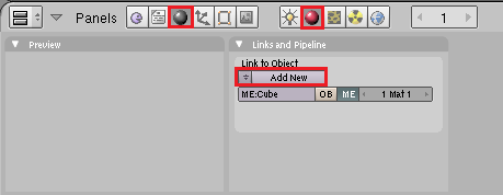
In the "Links and Pipeline" panel, under "Link to Object," click "Add New."
::在"链接和管道"面板中,在"链接到对象"下,点击"添加新".
-
Press
F6
to open the "Texture Buttons" panel or use the textures button.
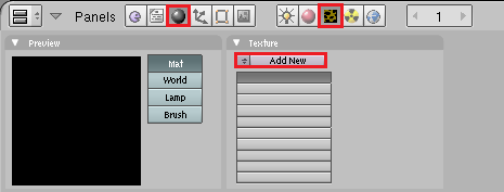
::按F6打开"纹理按"面板或使用纹理按. -
In the "Texture" panel, click "Add New."
::在"文本"面板中,点击"添加新".
-
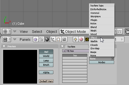
Change the "Texture Type" to "Stucci."
::改变"纹理类型"为"Stucci".
-
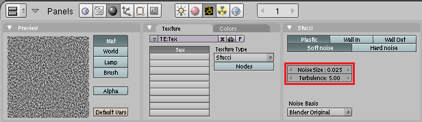
In the new "Stucci" panel, change "Noise Size" to something near 0.025 and leave the "Turbulence" at 5.00.
::在新的"Stucci"面板中,将"噪声大小"改为0.025附近的东西,并将"流"置于5.00.
Note: When finished with this section of the guide, come back to this panel and try different combinations of "Plastic," "Wall In," "Wall Out," and "Soft Noise" / "Hard Noise." Press F12 to render after each change to see the effect.
::按F12在每次更改后进行染, 查看效果. 按F12在每次更改后进行染, 查看效果.-
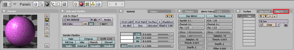
Press
F5
again or use the "Material" button directly on the left of the "Texture" button. Then look for the "Map To" panel.
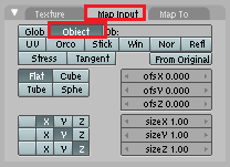
::然后使用"图像"按的左侧的"材料"按. 然后寻找"地图到"面板.
-
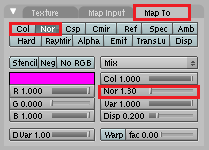
In the "Map To" panel, deselect "Col
[or]
" and select "Nor
[mal]
." and change the "Nor" Value to approximately 1.30.
::在"地图到"面板中,取消选择"颜色",选择"正常",并将"Nor"值更改为约1.30. -
In the "Map Input" panel, change the texture coordinates to "Object" by clicking the corresponding button.
::在"地图输入"面板中,通过点击相应按将纹理坐标更改为"对象". -
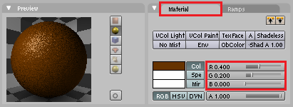
In the "Material" panel, change the "R
[ed]
" slider to approximately 0.400 and the "G
[reen]
" slider to approximately half that, about 0.200. Blue can be set at 0.00.
::在"材料"面板中,将"R[ed]"滑块变为大约0.400,而"G[reen]"滑块变为大约0.200. 蓝色可设置为0.00.
Note: While it is true that textures can only be applied to one object at a time, textures as well as materials can be shared between objects. In this case it is best to let both the head and the body share the same material.
::注意:虽然纹理只能一次应用于一个物体,但物体之间可以共享纹理和材料.在这种情况下,最好让头部和身体共享相同的材料.-
To do this, simply select the object without the materials(head or body).
::选择一个没有头部或身体的物体. -
Press
F5
to open the shading panel or use the shading panel button.
::按F5打开遮阳面板或使用遮阳面板按. -
In the "Links and Pipeline" panel, under "Link to Object," click the arrow next to(left of) the "Add New" button.
::在"链接和管道"面板中,在"链接到对象"下,点击"新增"按旁边的箭头. -
Select the brown material.
::选择棕色的材料.
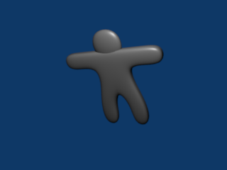
The steps in this section give a nicely textured, brown surface to the "Gingerbread."
::这部分的步骤给"饼"一个有质感的棕色表面.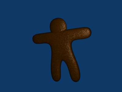
Now all you need to do is add eyes and gumdrop buttons!
::现在你只需要添加眼睛和糖果! -
Modeling a simple spaceship using Blender 2.49b
::使用Blender 2.49b建模一个简单的航天器This is a simple tutorial on how to build a simple spaceship using blender 2.49b. One of the best things about blender is the adaptability that can be accessed through its user interface. This tutorial will give you a look at some of the included blender scripts. If you would like to make your own, however, you can refer to the scripting chapter of this wiki book. So now, I guess we can get started.
::这是一个简单的教程,说明如何使用混凝土 2.49b 构建一个简单的太空船. 混凝土的最好的一点是通过其用户界面可以访问的适应性. 本教程将让您看看一些包含的混凝土脚本. 但是,如果您想自己制作,您可以参考本维基书的脚本章节. 所以现在,我想我们可以开始了.Step 1: First, open blender. You should get the default blender scene with the cube in the center. If you don't, try resetting your blender settings. Select the box in the center of the screen.
::步骤1:首先,打开混合器. 您应该得到中间立方体的默认混合器场景. 如果您没有,请尝试重置混合器设置. 选择屏幕中间的框.Step 2: Now we're going to shape the box into any shape we want. For now, we are going to shape it into a sort of triangle. If you want to use it as a box, that's fine, but I suggest following this tutorial using it as a sort-of triangle. To be able to modify it, in the lower buttons area (with stuff like Modifiers, Shapes, Multires, Mesh, and Link and Materials) you should see a drop-down menu that is currently on Object Mode. Change that to Edit Mode or hit the tab button. Now you will be able to modify different aspects of your box.
::步骤2:现在我们将把盒子塑造成我们想要的任何形状. 现在,我们将把它塑造成某种三角形. 如果你想把它用作盒子,那很好,但我建议你按照这个教程把它用作某种三角形. 为了能够修改它,在下面的按区域 (包含修改器,形状,多层,网格,链接和材料等东西) 你应该看到一个目前在对象模式上的下拉菜单. 将其更改为编辑模式或点击标签按. 现在你将能够修改盒子的不同方面.Step 3: With your box selected, hit Ctrl+Tab, and choose Faces. This allows you to modify the different faces. Faces are basically the different sides of your object, Edges are the edges of your object, and Vertices are points on your object where edges connect.
::步骤3:选择了框,按Ctrl+Tab,选择Faces. 这允许您修改不同的面. 面基本上是对象的不同侧面,边缘是对象的边缘,顶点是对象的边缘连接点.Step 4: Now, on your box, right click on one of the sides to select that side. If you want, first take a look around the box and then choose a side, but don't select the bottom or top face. To rotate around the box, hit the 8, 2, 4 or 6 button on your number pad, the one to the right of the arrow keys usually. Those buttons allow you to rotate around your objects and change your view. After you select the face you want, then rotate so that the face is facing towards you and looks like a square, and so that the grid around it looks like a flat horizontal line.
::步骤4:现在,在您的框中,右键单击侧面之一,选择该侧面.如果您愿意,首先看看框周围,然后选择侧面,但不要选择底部或顶部的面. 为了在框周围旋转,请按数字上的8,2,4或6按,通常是箭头键右侧的按. 这些按允许您旋转物体并更改视图. 选择您想要的面部后,然后旋转,使面部朝向您,看起来像一个方形,使周围的网格看起来像一个平坦的水平线.Step 5: There should be three arrows converging in the center of your face (or in the center of your box), and either the red or the green one should now be in the center of your face, and the other should be going off to the left or right, with the blue arrow going straight up or straight down. Use the 4 or 6 number pad button to rotate your view so you can see whichever arrow was in the center of your face, and left click mouse button on it, and hold the left click button, and drag the arrow around. Drag it until you have a rectangle. http://i238.photobucket.com/albums/ff55/bryguy336/uh.png http://i238.photobucket.com/albums/ff55/bryguy336/box.png
::步骤5:应该有三个箭头在你的脸的中心汇聚 (或在你的盒子的中心),红色或绿色现在应该在你的脸的中心,另一个应该是向左或向右移动,蓝色箭头直上或直下.使用4或6号码的按旋转你的视图,这样你就可以看到哪个箭头在你的脸的中心,然后左键鼠标按,并保持左键按,并拖动箭头. 拖动它直到你有一个矩形.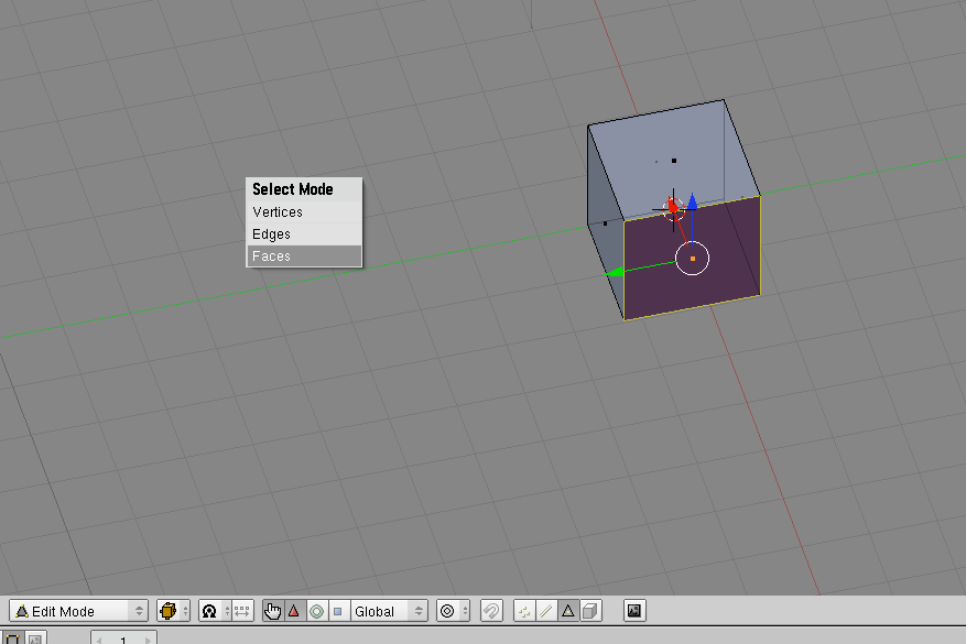 http://i238.photobucket.com/albums/ff55/bryguy336/png.
Step 6: Now to resize that face. With that face still selected, hit the S key, and move the mouse around. This should enable you to change the size of the face, and once you click, it should stop resizing and stay at that size. Experiment and get the hang of it, and then resize it so that it is an itsy bitsy teeny tiny box, and your rectangle more like a triangle. Congratulations! You have just made your first shape/object
::步骤6:现在要调整面孔的尺寸. 面孔仍然被选择,按下S键,并移动鼠标. 这应该使您能够改变面孔的尺寸,一旦您点击,它应该停止调整尺寸并保持在该尺寸. 实验并得到它的挂,然后调整它,使它是一个小小的小盒子,你的矩形更像一个三角形. 恭喜你! 你刚刚创造了你的第一个形状/对象
-
This is my first tutorial. I'll be teaching you to create this -
The quality is low because it is a gif. if it's a png or avi the quality'll be much better.
这是我的第一个教程。我将教你创建这个-质量很低,因为它是一个gif。如果是PNG或avi格式,质量会好得多。
-
Alright, this is my first tutorial here, I made this a while back, but hopefully it will be a good addition to this Wikibook. It was originally made for a game called Fable - The Lost Chapters , but I think it is worthy of another place in the world. Please note that this is a WIP and will be updated time to time.
::,这是我第一次的教程,我在不久前做了这个,但希望它能成为这个Wikibook的好补充.它最初是为一个名为Fable - The Lost Chapters的游戏而制作的,但我认为它值得在世界上其他地方使用.请注意,这是一个WIP,并将不时更新.Modeling Technique 1
::模拟技术1Modeling Technique 1 Part 1 Video
::模拟技术第一部分1视频Part 1:
::第1部分:-
After emptying the screen, go to view and click background image, load, then choose a picture of the weapon you want
::后, 扫描屏幕, 进入视图, 点击背景图像, 载入, 然后选择图片的武器你想要 -
Go to top view and add a square, then delete two of the vertices and place one of the remaining on a point on the picture, and the other out of the way.
::移动至顶部视图,添加一个方形,然后删除两个顶点, -
Select both vertices and subdivide.
::选择两个顶点并进行分类. -
Move the generated point to the next good-looking spot on the picture
::移动生成点到图片上的下一个好看的地方 -
With that selected still, select the outside vertex also, and subdivide.
::选择外顶,然后再进行分类.
(Note: A much easier way is to select one vertex, move it to where you want it, select the other vertex, move it to the next spot, then extrude the second vertex to the next point, rinse and repeat. This requires a lot less effort.) Another guy's note: For an easier way, just click CTRL+LMB where you want the next point to appear.
:-
Continue until you are on your third to last one, then select your outside vertex and move it where you would move the next vertex.
::然后选择你的外顶, 并将其移动到你将移动下一个顶点的地方. -
Select the first and last vertices and go to mesh>>make edge/face
::选择第一个和最后一个顶点,然后去网格> 制作边缘/面部 -
Extrude to half your preferred thickness, then extrude the rest of the way.
::挤出到你喜欢的一半厚度,然后挤出剩下的路. -
Select the center vertices on the blade, and scale up.
::选择刀片上的中心顶点,并缩放.
Modeling Technique 1 Part 2
::模拟技术1第二部分Part 2:
::第二部分:cont.)
::没有.-
Then move vertices to your liking.
::然后按照自己的喜好移动顶点. -
Select the vertices of the handle, go to mesh>>vertices>>separate.
::选择的顶点,进入网格>顶点>分离. -
Add a modifier, choose subSurf, turn up the level until it looks close to what you want without too many vertices. Click apply next to the modifier.
::在修改器旁单击应用. 添加修改器,选择SubSurf, 升级到接近你想要的水平, 没有太多的顶点. -
Modify vertices (using proportional edit helps) to your liking.
::根据自己的喜好修改顶点 (使用比例编辑帮助). -
Go to object mode, and turn off double-sided on any meshes that are.
::关闭任何双面网格的双面网格. -
If black appears on any parts of the mesh, highlight it, go to edit mode, select all vertices, go to mesh>>normals>>recalculate outside.
::如果黑色显示在网格的任何部分, 突出显示, 进入编辑模式, 选择所有顶点, 进入网格>正常>重新计算. -
If there is still black, select those faces and go to mesh>>normals>>flip.
::如果还有一些黑色, 选择这些面孔, 进入网格>正常>翻转. -
If there is still black, then you are missing a piece of mesh. Highlight the vertices around the hole, go to mesh>>vertices>>fill.
::需要在洞周围的顶点上亮点,然后进入网>>顶点>>填充. -
If black did not appear, then select everything (in object mode) and go to object>>join objects and say yes.
::如果黑色不出现,请选择所有 (在对象模式下) 并进入对象>加入对象并说是.
Modeling Technique 2
::模拟技术2Video Here Download it for high quality.
::视频 在这里Blade:
::刀片:-
Select all with the 'A' key, and delete everything.
::选择所有与"A"键,并删除一切. -
Go to view and choose background image >> use background image >>load and pick the sword you'll be doing.
::选择背景图像>使用背景图像>加载,然后选择你要使用的剑. -
Close the dialog after you see it in the background (you can change the brightness of it by changing the 'blend' option)
::关闭对话框后,你看到它在背景 (你可以通过改变'混合'选项来改变它的亮度) -
Make a bezier circle by pressing spacebar and going to add>>bezier>>bezier circle.
::通过按空格,并将"加"的"贝齐尔"圆圈, 创建一个贝齐尔圆圈. -
put a bar at each main point of your weapon (anywhere the curve changes direction)
::在你的武器的每个主要点 (曲线改变方向的任何地方) 放置一个条
Bezier Controls
::贝齐尔控制-
Modify the bars until they match.
::修改条形,直到它们匹配. -
You might want to go into wireframe view.
::你可能想进入线框视图. -
Go down and turn up the bevel depth a little, to give it some sharpness.
::让它变得更加利. -
To lower the poly count you should turn down the DefResolIU number.
::为了降低多元数,你应该把 DefResolU 号码降低. -
Go back to object mode, hit spacebar, go to object>>convert object type>>to mesh.
::返回对象模式,按空格,进入对象>转换对象类型>到网格. -
Modify vertices to your liking.
::根据自己的喜好修改顶点.
For the handle:
::对于手柄:-
Do steps 1-7.
::执行第1至第7步. -
Turn up the bevel resolution, to give it some roundness.
::提高形分辨率,使它变得更加圆. -
Repeat steps 8-10
::重复第8至10步
For That one thing (see video):
::对于这件事 (见视频):Just watch the video, but here is a summary.
::只是看一下视频,Extrude and flatten a circle, use proportional edit to make it easier on you when you curve the circle.
::通过比例编辑, 方便你在圆形上曲线.For hilt guard:
::对于手柄保护:-
Repeat steps 1-6
::重复第1至第6步 -
Add some extrusion.
::加入一些挤出. -
Repeat steps 8-10.
::重复第8至10步.
-
After emptying the screen, go to view and click background image, load, then choose a picture of the weapon you want
-
Getting started
::开始To begin, open a new scene in Blender. Let's clean up the scene a little by selecting the lamp and camera in the scene, press M to move them to a different layer and click on the fifth layer from the left to place the objects. Go back to layer 1 and delete anything else. You may also want to get rid of the grid by opening the View Properties and turning off the Grid Floor and X & Y axes.
::首先,在Blender中打开一个新场景. 让我们稍微清理场景,选择场景中的灯和摄像头,按M将它们移动到不同的层,然后点击左侧的第五层放置对象. 回到第1层并删除其他任何东西. 您也可以通过打开视图属性并关闭网格地板和X和Y轴来消除网格.To block out our character, we're going to use an object type that is probably the least used and useful of any known to mankind. Let's hear it for... Metaballs!
::为了阻止我们的角色, 我们将使用一种对象类型,Sculpting With "Lumps of Clay"
::用"泥块"雕刻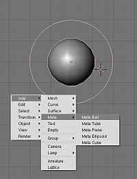
Go into the top view (important), press Space and add a metaball. Metaballs are a nifty, ancient piece of 3D technology that is useful for creating blobs. (Similar to lumps of clay, eh?) You create simple primitive shapes and scale and rotate them to block out your character's shape. When the primitives come close to one another, they "bleed into one another" in much the same way that water droplets merge when they touch. Cool.
::进入顶部视图 (重要),按空格并添加一个metaball.metaballs是一个很棒的,古老的3D技术,它是有用的创建斑点. (类似于粘土块,?) 你创建简单的原始形状和规模,并旋转它们来阻止你的角色的形状.当原始人接近彼此,他们"流血到彼此"的方式与水滴合并当他们碰.酷.If you're using an earlier version of Blender that jumps out of Object mode into Edit mode when you create an object, then press Tab to switch back to Object mode, as you won't be able to scale your Meta primitive non-proportionally in Edit mode.
::如果您使用的是早期版本的Blender,在创建对象时将其从对象模式跳转到编辑模式,请按Tab转回对象模式,因为您无法在编辑模式中非比例地缩放您的Meta原始.In Object mode, you can change these options for the entire Meta object, while tabbing into Edit mode gives you more options for the selected meta primitive, such as changing the type from Ball to Tube, Plane, Cube, ;;etc.; (You can also make "Negative metaballs.")
::在Object模式下,你可以为整个Meta对象更改这些选项,而在Edit模式下,你可以为所选的元原始类别提供更多选项,例如从Ball更改为Tube,Plane,Cube等. (你也可以制作"负元球").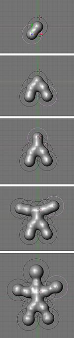
Press Shift+D to duplicate the Metaball, and place it where you like. Continue blocking out your character, building enough blobs to represent the limbs or forms you will need to sculpt your masterpiece.
::按Shift+D复制Metaball,然后将其放置在您喜欢的地方.继续阻止您的角色,建立足够的斑块来代表您需要雕塑杰作的四肢或形状.The balls at the end of the limbs, were scaled SKEY larger, and then moved GKEY out a bit more.
::脚的球被缩小了,然后把GKEY移出了.Don't get carried away and put in too much detail at this stage: use as few shapes as you need. (This is supposed to be quick and fun, after all...)
::现在不要太过详细,只要需要,就尽量少用形状. (毕竟,这应该是快速而有趣的...)Meta-mess!
::没有任何东西!You should still be in object mode.
::你应该仍然在对象模式.Now that you've got something that resembles what you're after, select all the Metaballs and ( be in object mode) type ALT+C -> "delete original", to convert it to polygons so you can actually do something with your blob.
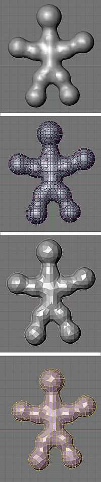
::选择所有元球,然后 (在对象模式下) 键入ALT+C -> "删除原始", 将其转换为多边形,Noob note: if you pick "keep original" you will still have the meta balls present, plus have a mesh version of the metaballs sharing exactly the same space. When you select "delete original", the meta balls are turned into the mesh, and the circles that the metaballs were originally in hang around, but are empty.
::笔记:如果选择"保留原始",你仍然会有元球,还有一个共享完全相同空间的元球的网格版本.当您选择"删除原始"时,元球会变成网格,而元球原来在的圆圈会悬挂,但空.
Still in object mode!
::仍然在对象模式!Delete any of those black rings left over from the metas and select your new polygon mesh.
::删除任何从超人剩下的黑色环, 选择你的新多边形网.If you Tab into Edit mode you will see terrifying ugliness instead of nicely gridded mesh. "Surely we can't be expected to create anything useful out of this!" you shriek. Take it easy, my friend. It's time to add a Decimate modifier (make sure you're in object mode when doing this to see changes).
::如果你在"编辑"模式下,你会看到可怕的丑,而不是精美的网格. "我们不能期待从中创造出任何有用的东西!"你尖叫. 放心吧,我的朋友. 现在是时候添加一个 Decimate 修改器了 (确保在做这个时你处于对象模式以查看更改).Switch back to object mode!
::切换回对象模式!The Decimate modifier (you will only see things change if you're in object mode) will do two things for us. Its primary job is to reduce the poly count of a mesh. A pleasant side-effect for our purposes is that it will begin to rearrange the topology into a more manageable heap of triangles and quads. Keep reducing the Ratio slider below 0.5 until it becomes as coarse as you can stand. You want the lowest polygon base you can have that still maintains enough detail in the limbs and shapes you made with the Metaball phase.
::十进制修改器 (只在对象模式下才会看到变化) 将为我们做两件事.它的主要任务是减少网格的多元数.一个令人愉快的副作用是它将开始重新排列拓,使其成为一个更容易管理的三角形和四角形堆.一直将比例滑块降低到0.5以下,直到它变得尽可能粗.你想要你能拥有的最低的多边形底部,仍然保持足够的细节在Metaball阶段所做的四边形和形状中.One thing to watch for is that this process sometimes creates holes as it does its best to simplify the mesh. I find that usually you can slightly change the Ratio to fix the problem, but if you're still finding holes, check out the "Tips & Tricks" section at the end.
::需要注意的一点是,这个过程有时会产生洞,因为它尽其最大努力简化网格.我发现通常你可以稍微改变比例来解决这个问题,但如果你仍然发现洞,请查看最后的"提示和技巧"部分.As you can see, this step greatly reduces the Face Count, which will be good later. Next we need to get rid of as many of those triangles as possible. Click Apply (in the modifier panel)
::现在我们需要尽可能多的三角形. 单击应用 (在修改器面板中)Switch to Edit mode!
::切换到编辑模式!Press A until all of the vertices are selected (turn yellow) and hit Alt-J to convert the faces from triangles to quads, which will subdivide better. Now you should have something you can work with.
::按A,直到所有的顶点被选中 (变成黄色),然后按Alt-J,将面从三角形转换为四角形,这将更好地分为部分.现在你应该有可以使用的东西.Beginning to sculpt
::开始雕塑Right next to the Modifiers panel is the Multires panel. (Note: In recent versions of Blender this is not its own panel---it is a Modifier.) A multires object has the options to add numerous levels of smooth subdivision to a mesh. While you can use the sculpt tools on any polygon or nurbs mesh, the great strength of sculpting with Multires is the ability to jump back and forth to different levels, quickly sketching out the gross form at lower levels, and adding finer detail at the higher levels. Add the Multires and Add a level; we're ready to sculpt!
::修改器面板旁边是多层面面板. (注意:在最近的版本中,Blender不是自己的面板,它是一个修改器.) 多层面对象有选择为网格添加多个平滑的分级.虽然你可以在任何多边形或nurbs网格上使用雕塑工具,但多层面雕塑的强大优势是能够跳向不同层面,快速绘制低层的粗体形式,并在高层添加更细致的细节.添加多层面和添加一个层面;我们准备好雕塑!- Noob note: If nothing seems to be happening while you're trying to sculpt your mesh, it's because you haven't applied your Decimate. it must be locked down and applied before you're actually allowed to do anything to your mesh.
- Noob note: Only apply multires once, doing it a few times will quickly increase the polygon count to amounts that will really slow blender down
In case you haven't noticed, Blender's different modes offer different tool sets and options. To make the sculpting tools available you need to be in Sculpt mode, accessible through the Mode drop-down in any 3D window header. You'll see two new tabs next to the multires panel, Sculpt and Brush. Sculpt has most of the options you'll need to begin shaping your mesh. Note that most of the different brushes in this panel have hot-keys which will save a lot of time( G =Grab, D =Draw, S =Smooth, etc. ). Most important here is changing the brush size and intensity. Pressing F and dragging the mouse will resize the brush, while Shift-F will allow you to adjust the Brush Intensity. You can also turn on Symmetry to paint, for instance, both sides of a face at one time. This can speed up tasks tremendously, as long as your mesh is aligned to the axis properly.
::对于使用者来说,Blender 的不同模式提供了不同的工具集和选项. 要使雕塑工具可用,您需要在 Sculpt 模式中,可以通过任何 3D 窗口标题中的 Mode 下拉窗口访问. 您将在多层面面板旁边看到两个新选项标签,Sculpt 和 Brush. Sculpt 具有您开始塑造网格所需的大部分选项. 请注意,这个面板中的大多数不同刷具有热键,这将节省大量时间 (Grab=Grab, D=Draw, S=Smooth 等). 最重要的是改变刷子的大小和强度. 按 F 拖动鼠标将调整刷子的大小,而 Shift-F 将允许您调整刷子强度. 您还可以在 Symmetry 上同时转动,例如 -
Match moving is the technique of recreating the position of the camera used in recording live action footage. This information can then be used within Blender to merge 3D objects with live action film. For a more detailed discussion of the concept, take a look at the Wikipedia article on Match Moving .
::移动匹配是用来记录实时动作片段的摄像头位置的复制技术.此信息可以在Blender中用于将3D对象与实时动作片合并.对于更详细的概念讨论,请参阅维基百科关于匹配移动的文章.Blender cannot perform match moving itself, you must use a 3rd party tool to determine the camera position and the way it moves, then import this data into Blender. While there are many software tools to do this, this page references two free options: Voodoo and Icarus.
::Blender不能自行进行匹配移动,您必须使用第三方工具来确定摄像头位置和移动方式,然后将这些数据导入Blender.虽然有许多软件工具可以做到这一点,但本页面引用了两个免费选项:Voodoo和Icarus.Icarus
::伊卡洛斯Icarus is a discontinued University of Manchester project which can be used for non-commercial work. The download links from the official page no longer function, but Windows and MacOS X versions are available from this Icarus video tutorial by Colin Levy.
::伊卡鲁斯是一个已停产的曼彻斯特大学项目,可用于非商业工作.官方页面的下载链接不再工作,但Windows和MacOS X版本可从Colin Levy的Icarus视频教程中获取.Voodoo
::巫术Voodoo is an actively developed free match mover available for Windows and Linux. Here is a tutorial on using Voodoo and Blender
::伏是一个主动开发的免费的匹配移动器,可用于Windows和Linux. 以下是关于使用伏和Blender的教程
-
Motion tracking , also called Match moving , is an essential element when integrating 3D elements with live footage. Motion tracking software is usually pretty expensive, but the Icarus application (Windows and Mac) is available for free for educational use. Icarus, which hasn't been updated for while, was later replaced by the commercial application PFTrack . Other popular motion tracking applications are PFMatchit and PFHoe (both also from The Pixel Farm), Voodoo (for Windows/Linux; free for non-commercial use), SynthEyes , Boujou and 3D-Equalizer (commercial).
::运动跟踪,也称为匹配移动,是将3D元素与实时录像集成时的必不可少的元素.运动跟踪软件通常相当昂贵,但Icarus应用程序 (Windows和Mac) 可免费用于教育用途.Icarus,这已经没有更新,后来被商业应用程序PFTrack取代.其他流行的运动跟踪应用程序是PFMatchit和PFHoe (这两者也是来自Pixel Farm),Voodoo (Windows/Linux;免费非商业用途),SynthEyes,Boujou和3D-Equalizer (商业).The excellent CG prodigy Colin Levy hosts Icarus(by kind permission of The Pixel Farm Ltd), the Icarus import script for Blender, as well as a splendid video tutorial (see Download Icarus and Video Tutorial ). However, I lacked a brief text tutorial about motion tracking, so I decided to write my own. This tutorial is extremely brief and high-level, and requires some previous knowledge on video editing, 3D, and Blender.
::优秀的CG神奇人物科林·莱维主持了Icarus (通过Pixel Farm Ltd的许可),Blender的Icarus导入脚本,以及一个精彩的视频教程 (见下载Icarus和视频教程).然而,我缺乏关于运动跟踪的简短文本教程,所以我决定写自己的.这个教程非常简短和高级,需要一些关于视频编辑,3D和Blender的先验知识.Note: this tutorial was created using Mac OS X 10.5 Leopard, Blender 2.46, Icarus 2.09, and the Icarus Import Script for Blender v1.07e (for Blender 2.41, written by Alfredo de Greef).
::注意:本教程使用Mac OS X 10.5 Leopard,Blender 2.46,Icarus 2.09,以及Blender v1.07e的Icarus 导入脚本 (为Blender 2.41编写的Alfredo de Greef) 来创建.Tutorial
::导学Phase 1: Preparing the Video Footage
::第一个阶段:制作录像Note: this tutorial explains the Auto-feature Tracking mode in Icarus. There are other options which gives more user control - see the Icarus UserGuide.pdf for more information.
::注意:本教程解释了Icarus的自动功能跟踪模式. 还有其他选择可以让用户有更多的控制权 - 查看Icarus用户指南.pdf获取更多信息.-
Record your video footage. Having the camera on a tripod (thus limiting to just panning/rotating) simplifies the tracking, but Icarus can handle a hand-held camera as well. Filming a background with orthogonal lines (that can align to X/Y/Z dimensions), such as a room, also helps the tracking.
::记录你的视频录像. 设置摄像机在三脚架上 (因此仅限于旋转/旋转) 简化了跟踪,但Icarus也可以处理手持摄像机. 拍摄一个背景与直角线 (可以对齐到X/Y/Z维度),如一个房间,也有助于跟踪. -
Capture/import your video footage to your computer. Icarus handles video up to DV resolution (720*576 pixels).
::捕捉/导入您的视频录像到您的计算机. Icarus处理视频高达DV分辨率 (720*576像素). -
Start the Icarus
Calibration
application (there is also a
Distortion
and a
Reconstruction
application).
::启动"伊卡鲁斯校准"应用程序 (还有一个"扭曲"和"重建"应用程序). -
Create a new project (Project->New).
::创建一个新项目 (项目->新). -
Import your video footage (Project->Import Movie).
::导入您的视频录像 (项目-> 导入电影). -
Fill in the
Camera Parameters
information in the window that pops up - especially the
Camera Motion
and the
Pixel Aspect
options.
::在弹出窗口中填写相机参数信息 - 特别是相机运动和像素方面选项. -
In the left panel, expand the group called
Coordinate Frame
. You should see X Axis, Y Axis, etc.
::在左面板中,扩展名为坐标框架的组. 你应该看到X轴,Y轴等等. -
Click the Z Axis tool (blue) and mark vertical lines in your video footage. Use the X Axis (red) and Y Axis (green) tools to mark horizontal lines (up to you to decide which should be X and Y).
::点击Z轴工具 (蓝色) 并在视频中标记垂直线.使用X轴 (红色) 和Y轴 (绿色) 工具标记水平线 (由您决定哪个应该是X和Y). -
Estimate the focal length (Camera->Estimate Focal Length).
::估计焦距 (摄像机->估计焦距). -
Navigate in time in your video footage using the time slider (beneath the video image). Add more X/Y/Z marker lines on a few key frames, especially as new pieces of the background are revealed when the camera moves.
::在视频中使用时间滑块 (视频图像下方) 导航时间. 在一些关键上添加更多的X/Y/Z标记线,特别是当摄像机移动时,会发现新的背景片段. -
Save your project (Project->Save).
::保存您的项目 (项目-> 保存). -
Start the tracking process (Camera->Track and Calibrate). This will take some time.
::启动追踪过程 (摄像机->追踪和校准). 这需要一些时间. -
Export the results in human-readable form (Project->Export 3D Motion, select
Human Readable (*.txt)
as file type).
::将结果导出为人类可读的形式 (Project->导出3D动作,选择人类可读 (*.txt) 作为文件类型).
Phase 2: Importing the Motion Tracking Data into Blender
::阶段2:将运动跟踪数据导入混器-
Start Blender, and open a Text Editor view.
::启动Blender, 打开一个文本编辑器视图. -
Open the Icarus import script
ICARUS_import241.py
(File->Open).
::打开"伊卡鲁斯"导入脚本ICARUS_import241.py (文件->打开). -
Start the script (File->Run Python Script). You should now see the Icarus Import screen.
::现在你应该看到"伊卡鲁斯导入"的屏幕. -
Press the
FSEL
button, and open the results you exported from Icarus.
::按FSEL按, 打开从Icarus导出的结果. -
Press the
Create Curves
button. This imports the camera motion from the Icarus data and applies it to the Blender default camera.
::按下"创建曲线"按. 这将从Icarus数据中导入摄像机运动并将其应用到Blender的默认摄像机. -
Press the
Feature Points Mesh
button. This imports 3D shape dots from the Icarus data, which helps as reference when you want to align your own 3D elements to the video footage.
::按下"特征点网格"按. 这将从Icarus数据中导入3D形状点,当您想要将自己的3D元素与视频镜头对齐时,这有助于参考.
You are now ready to add your own 3D elements to the Blender scene.
::现在您可以为Blender场景添加您自己的3D元素.Phase 3: Compositing 3D Elements on top of Video Footage
::阶段3:在视频录像上组合3D元素If you want to easily composite the 3D elements on top of an image, you can add the image as the rendering back buffer in Blender (Scene tab in the Buttons view). However, this doesn't work for videos, so we need another solution.
::如果您想在图像顶部轻松组合3D元素,您可以在Blender中添加图像作为染回缓冲区 (按视图中的场景选项卡). 然而,这对视频不起作用,因此我们需要另一个解决方案.-
In Blender, switch to
SR:4 - Sequence
in the layout dropdown menu at the top of the screen.
::在Blender中,在屏幕顶部的布局下拉菜单中切换到SR:4 - 序列. -
In the
Video Sequence Editor
view (middle of screen), add your video file (Add->Movie). Move the new strip to layer 1, frame 1.
::在视频序列编辑器视图 (屏幕中间),添加您的视频文件 (添加-> 电影). 将新条带移动到1层,1. -
Add the current scene to the sequence (Add->Scene, Scene). Move the new strip to layer 2, frame 1.
::将当前场景添加到序列 (添加->场景,场景). 将新条带移动到2层,1. -
Select the scene strip on the second layer (right-click).
::在第二层选择场景条 (右键). -
Open the
Scene
panel in the Buttons view, and then open the
Sequencer
sub-panel.
::然后打开序列分组. -
Change the
Blend Mode
dropdown from
Replace
to
Alpha Over
. Your 3D elements should now render over the background video in the top-right preview screen.
::现在,您的3D元素应该在右上方的预览屏幕上呈现背景视频. -
In the Render panel, enable
Do Sequence
just below the ANIM button. This will enable the background video when rendering.
::在染面板中,在ANIM按下方启用"执行序列". 这将在染时启用背景视频.
Troubleshooting
::解决问题-
If your imported Feature Points Mesh looks a bit spherical, you need to generate camera distortion data using the Icarus
Distortion
application.
::如果您的导入的特征点网看起来有点球形, 您需要使用Icarus Distortion应用程序生成相机扭曲数据.
-
Record your video footage. Having the camera on a tripod (thus limiting to just panning/rotating) simplifies the tracking, but Icarus can handle a hand-held camera as well. Filming a background with orthogonal lines (that can align to X/Y/Z dimensions), such as a room, also helps the tracking.
-
Subsurface modeling
::地下模型Organic modeling is considered by some the most challenging. Non-organic can mostly be accomplished by extrusion and scaling. Organic modeling on the other hand involves mainly curves, as nature has a thing against straight lines. Because of this, organic modeling is usually done with subsurfaces. To subsurf a mesh, first select it and navigate to the 'Editing' tab. Then go to the modifiers stack and add a new Subsurf modifier.
::有机建模被一些人认为是最具挑战性的.非有机可以通过挤出和缩放来完成.另一方面,有机建模主要涉及曲线,因为自然对直线有异议.因此,有机建模通常使用地表进行.要进行网格的地表,首先选择它并导航到'编辑'选项卡.然后进入修改器堆并添加新的Subsurf修改器.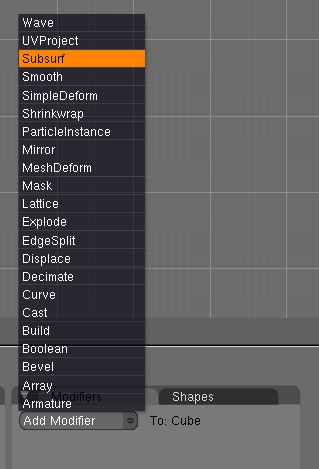
In Blender 2.5 Alpha 0, Subsurf has been removed from the modifiers list. Instead hit Ctrl, followed by a number which will specify the subsurf level. For example Ctrl-1 adds a new Subsurf modifier of level 1. This also works in Blender 2.4. Increasing the level greatly increases the number of verts in your model, so make the level relative to the number of vertices in your original model (pre-subsurfed). Subsurf often works best in conjunction with smoothing, so be sure to set your object to smooth, again in the 'Editing' tab, or in 2.5 A0 under 'Object Tools', which you can bring up by hitting the T key in the 3D viewport.
::在Blender 2.5 Alpha 0中,Subsurf已从修改器列表中删除.相反,按Ctrl,然后按一个数字来指定Subsurf级别.例如Ctrl-1添加了一个新的Subsurf修改器,该级别为1. 这也在Blender 2.4中工作.增加级别大大增加了模型中的顶点数,因此使水平相对于原始模型中的顶点数 (预先进行了subsurf). Subsurf通常与光滑一起工作,所以请确保将对象设置为光滑,再次在'编辑'选项卡中,或在2.5A下'对象工具',您可以通过在3D视图端口中按T键来提升.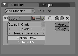
In this way you can create a smoother, higher-poly shape based on that of the original mesh. This is controlled by the vertices, edges and faces of the original.In order to control the rounding of your mesh you can use two methods: loopcuts, which is a very sloppy method as it adds more verts to your mesh, which serve very little purpose and can get in the way of modeling; and Edge Creasing. The latter can work extremely well in most circumstances. By default all edges are declared uncreased, and so allow complete rounding in subsurfing, by creasing the edges using Shift-E you can far better control the amount of rounding on your mesh, and most importantly, without adding extra vertices. However, unfortunately Edge Creasing is not available in Blender 2.5 A0. Yet. And so loopcuts and extra verts are the only option.
::通过这种方式,您可以根据原始网格的形状创建更光滑,更高的多元形状.这是由原始网格的顶点,边缘和面部控制的.为了控制网格的圆形,您可以使用两种方法:循环切割,这是一个非常粗略的方法,因为它为您的网格添加了更多的顶点,这很少有目的,并且可以在建模过程中得到;和边缘纹.后者可以在大多数情况下工作得非常好.默认情况下,所有边缘都被声明为未增加,因此允许在地下进行完整的圆形,通过使用Shift-E纹边缘,您可以更好地控制网格上的圆形数量,最重要的是,不添加额外的顶点.然而,不幸的是,边缘纹在Blender-
 Before
::在之前 -
 After
After
::在之后
Now, start shaping your mesh into an organic shape. There are various tutorials for modeling bodies and faces, but it is often a good idea to use references. Only use quads - that is, shapes with four vertices. Triangles do not subsurface well, they create bad looking rough surfaces - avoid if at all possible. Also avoid Poles, which are vertices connected to anything other than 2 or 4 other vertices, as they create literal creasing in your subsurfed mesh, that is, sudden bunching up and pinching of faces.
::现在,开始将网格塑造成有机形状. 有各种教程可以模拟身体和面部,但经常使用参考是个好主意. 仅使用四角形 - 即四个顶点的形状. 三角形不好地下,它们会产生不好看的粗表面 - 如果可能的话,尽量避免. 还要避免极点,它们是连接到2或4个顶点以外的顶点,因为它们会在你的地下网格中产生字面上的纹,即突然结和结面部.To make the object shape properly, you will need good edgeloops and edgeflow. This means that all your vertices and/or faces line up in a continual line or curve around your model. It is possible to select edgeloops all in one, fantastic when you have to resort to them in controlling rounding, by holding down Alt when selecting a vert. This really expands into topology, which is an advanced subject. I would recommend visiting http://www.subdivisionmodeling.com/forums , although it has just been closed down, which was a great place to start, however it still (at the time of revision) is active and well worth a look if you are struggling with modeling heads. It is best not to have too many vertices to avoid making the subsurfaced shape look rough - in other words, the original shape should be quite low-poly.
::为了使物体形状正确,你需要良好的边缘环和边缘流. 这意味着所有顶点和/或面都排成一条连续的线或曲线绕着你的模型. 通过选择一个顶点时按住Alt,可以选择边缘环全部,当你必须在控制圆形时使用它们时很棒. 这真的扩展到拓学,这是一个高级主题. 我建议访问http://www.subdivisionmodeling.com/forums,尽管它刚刚关闭,这是一个很好的起点,但它仍然 (在修订时) 是活跃的,如果你正在努力模拟头部,最好不要有太多的顶点,以避免使地下表面看起来粗 - - 换句话说,原来的形状应该相当低多元.
-
-
Understanding the Fluid Simulator
::了解流体模拟器When I first encountered the Fluid Simulator I had a hard time understanding its behavior, especially the Start time and End time didn't seem to make any sense at all. Going on a Google spree revealed that many people have problems figuring out the secrets behind fluid simulation, and I didn't find any truly helpful guides. In this little guide I'll try to explain it in a newbie friendly way. It may not be entirely correct, although it might help newbies understanding how it works.
::当我第一次遇到流体模拟器时,我很难理解它的行为,特别是开始时间和结束时间似乎没有任何意义. 谷歌的狂热显示,许多人有困难弄清楚流体模拟背后的秘密,我没有找到任何真正有用的指南. 在这个小指南中,我将试图以新手友好的方式解释它. 它可能不完全正确,尽管它可能有助于新手了解它如何工作.First of all
::首先Start time and End time are in seconds. Don't forget this. Even if your simulation seems to go insanely fast when you set Start time to 0 and End time to 10 and having 250 frames in your animation with 25 frames per second, there is a good reason for this. For now, just remember this, don't let your mind wander and believe that the values are in milliseconds or that you have to do some wicked math dividing/multiplying with frames and so on.
Also notice that the domain is the bounding box for the whole fluid calculation. EVERYTHING is done inside this box. It acts as the floor, ceiling and walls for all of the fluid. This is very important, as the number 1 reason why I couldn't get a good fluid simulation going. If I have time, I will do a section on Fluid > Control, but for now, I will say that it adds a LOT of calculation time. Running on an I7, ATI Radeon 8970 Video, Asus P6X58D Premium, 64-bit Windows 7 and 64-bit Blender, I crashed my computer with the lowest quality settings. So just remember that the domain MUST surround the area in which you do calculations. Also note that after you set up your simulation, the domain becomes the actual liquid, so give it proper material and try not to bake until you're pretty sure of your simulation.
::开始时间和结束时间是以秒数计算的. 不要忘记这一点. 即使当你将开始时间设置为0和结束时间设置为10并且动画中有250,每秒25时,你的模拟似乎会非常快,这也是有充分的理由的. 现在,请记住这一点,不要让你的头脑,认为这些值是以毫秒数计算的,或者你必须用做一些邪恶的数学除法/乘法等. 还要注意,域是整个流体计算的边界框. 每个东西都是在这个框内完成的. 它作为所有流体的地板,天花板和墙壁. 这非常重要,因为这是我无法获得一个好的流体模拟的第1个原因. 如果我有时间,我会在流体控制上做一个很好的操作,但现在我会说它Setting up the scene
::准备情景We'll learn how the fluid works the practical way. plane
::我们将学习如何流体工作的实用方式. 平面-
Start with the default box, this simulation will be very simple.
::这种模拟将非常简单. -
Let's work in wireframe mode, press the
ZKEY
to turn off solid mode.
::让我们在线框模式下工作, 按ZKEY关闭固体模式. -
Go in to camera view by pressing
Numpad0
.
::通过按下Numpad0进入摄像头视图. -
With the box selected, scale it up to two times by pressing
SKEY
, then
2
, then
ENTER
. This fits the camera fairly well.
::选择了框,按下SKEY,然后按2,然后按ENTER, 缩放到两次. 这适合相机. -
Press
Numpad7
for a top view.
::按Numpad7可以看到顶部. -
With the box selected, press
Shift-D
(don't move the mouse or else the duplicated box will move) then press
ENTER
to confirm the duplicated box's location. If you do move the box, just press
Escape
then the new box will be kept but the move cancelled.
::选择了该框,按下Shift-D (不要移动鼠标,否则重复的框将移动),然后按下ENTER以确认重复的框的位置.如果您移动了该框,只需按 Escape,则将保留新框,但移动将被取消. -
While the new box is selected (and in exactly the same spot as the other box), press
SKEY
, then
.5
, then
ENTER
to scale it to half size.
::在新框被选中 (与其他框完全相同的地方), 按SKEY,然后5.5,然后ENTER以缩小到半个尺寸. -
Stay away from the mouse, accuracy is important here and I'll explain why later.
::远离老鼠, 精确度是很重要的, -
Now we want to move the new box into one of the upper corners. Press the
GKEY
, then press the
XKEY
, type in
-1
, press
ENTER
and the box should move to the left wall of our larger box.
::现在我们要把新框移到上面的角落之一. 按GKEY,然后按XKEY,输入-1键,按ENTER,框应该移到我们较大的框的左边. -
We want the box in a corner, so press
GKEY Y 1 Enter
, the box should now be in the top left corner from our current view.
::现在该框应该在我们当前视图的左上角. -
However, we're in 3 dimensions, not 2 so click
Numpad1
for a side view. This time we'll move the box up along the Z-axis:
G Z 1 Enter
.
::现在我们在3维,而不是2维,所以点击Numpad1以获得侧面视图. 这次我们将框沿Z轴向上移动:G Z 1 Enter. -
Excellent, our setup is done.
::很好,我们的设置完成了.
Setting up the simulation
::设置模拟-
Make sure you're in Object Mode, and that you followed the above steps precisely.
::确保您处于对象模式, 并准确地遵循上述步骤. -
Select the smaller box and click
F7
twice. You should get a panel where the rightmost pane says "Fluid Simulation". Click
Enable
.
::选择较小的框,然后双击F7. 您应该看到一个右边窗格上写着"流体模拟". 点击启用. -
Our small box will be the fluid, so just click the
Fluid
button. That's all there is to do with the small box.
::只有点击"流体"按. -
Now select the large box. The Physics panel should still be visible, click
Enable
in the Fluid Simulation pane and then select
Domain
.
::现在选择大框. 物理面板应该仍然可见, 在流体模拟面板中单击启用, 然后选择域. -
By default your animation should have 250 frames. Rendering should also be set to 25 frames per second by default, this tutorial assumes this setup.
::默认情况下,你的动画应该有250. 染也应该设置为每秒25, 这个教程假设这个设置. -
Since we got 250 frames and 25 frames per second that means our animation is 10 seconds long. So here comes the tricky part, which actually isn't that tricky at all:
-
Start time is by default set to 0 seconds. This means that on the very first frame the simulation has just begun. You could increase this value to say, 1 second and that would mean that on the first frame the fluid simulation has already run for 1 second. We don't want to do this, so keep it at 0 seconds.
::启动时间默认设置为0秒. 这意味着在第一个中,模拟刚刚开始. 你可以增加这个值,说, 1秒,这意味着在第一个中,流体模拟已经运行了1秒. 我们不想这样做,所以把它放在0秒. -
End time is by default set to 0.3 seconds. What does this mean? This means that on the 250th frame the simulation has run for 0.3 seconds. However, by default our animation is 250 frames long with 25 frames per second, making those 0.3 seconds stretched over 10 seconds. Basically this means that we're watching the show in slow motion, or slightly less than 1/33 the realtime speed. So now you may think "it looks quite realtime to me!", and yes, it does, but why does it do that? Well, that's hard to explain. Consider this: In a world without friction, how far would a drop of water fall after 1 second? The answer is about 4.9 meters. So, if a drop of water falls from 4.9 meters it will take 1 second before it reach the ground. How long would it take the waterdrop to reach the ground if it falls from 3 centimeters? About 0.078 seconds. So why do i mention 3 centimeters? Because by default the size of our domain is 3x3x3 centimeters, or
really
small. If you're like me, you were probably thinking that the fluid was flowing around in a bathtub or a barrel, not in the wrapping of a cupcake.
Set
End time
to 10 seconds
.
::默认设置的结束时间为0.3秒. 这意味着什么? 这意味着在第250时,模拟运行了0.3秒. 然而,默认情况下我们的动画是250长,每秒25,使这些0.3秒延长了10秒. 这基本上意味着我们正在慢动作观看节目,或者略低于实时速度的1/33. 所以现在你可能会想"它看起来很实时!"是的,它确实如此,但为什么它会这样做? 好,这很难解释. 考虑一下:在没有摩擦的世界里,一滴水在1秒后会跌到多远? 答案是大约4.9米. 所以,如果一滴水从4.9米落下,它将需要1秒才能到达地面. 如果从3厘米落下,水流器
::既然我们有250和25每秒,这意味着我们的动画长10秒.所以这里是棘手的部分,这实际上不是那么棘手:开始时间是默认设置为0秒.这意味着在第一个的模拟刚刚开始.你可以增加这个值,说,1秒,这意味着在第一个的流体模拟已经运行了1秒.我们不想这样做,所以保持在0秒. 结束时间是默认设置为0.3秒.这意味着什么?这意味着在第250的模拟运行了0.3秒.然而,默认我们的动画长250每秒25,使这些0.3秒延伸到10秒.这基本上意味着我们正在看这个节目在运动中,或略低于1/33的实时速度.所以你可能认为"它 -
Start time is by default set to 0 seconds. This means that on the very first frame the simulation has just begun. You could increase this value to say, 1 second and that would mean that on the first frame the fluid simulation has already run for 1 second. We don't want to do this, so keep it at 0 seconds.
-
Since our imagination likes big things, let's crank up that cupcake to say, a swimming pool. Make sure the big box is selected in Object Mode In and look at the Fluid Simulation pane. Just to the left of the "BAKE" button there should be 3 other buttons, possibly named "St", "A", "B". Click
A
for advanced options.
::由于我们的想象力喜欢大东西,让我们把那个蛋糕打开,比如说,一个游泳池.确保在对象模式中选择大框,然后看看流体模拟窗口.在"BAKE"按的左边应该有3个其他按,可能名为"St","A","B".点击A以获得高级选项. -
Some new boxes should appear, Gravity (should be -9.81 for the Z-axis, nothing else), Water and the option we're looking for, "Realworld-size". Also Gridlevels and Compressibility, but let's not care about those now.
::应该出现一些新的框,重力 (应该是-9.81的Z轴,没有别的),水和我们正在寻找的选项",现实世界大小". 也格式和可压缩,但让我们现在不关心这些. -
The "Realworld-size" value says how large our domain is in meters, and as you can see it's 0.03 meters by default, or 3 centimeters. We want it huge, so crank it up to 10, which is the limit for Blender 2.45. Now our swimming pool is 10x10x10 meters (don't drown!), remember this because scale matters with fluid. Do not think we're playing with cupcakes again
::实体大小的值表示我们域的尺寸是多少, 默认是0.03米, 也就是3厘米. 我们想要它大, 所以把它调到10, 这是Blender2.45的限制. 现在我们的游泳池是10x10x10米 (不要淹死!), 记住这一点, 因为尺寸与液体有关. 不要认为我们再次玩蛋糕. -
Now click
BAKE
, and read on while your computer is chewing zeroes and ones.
::现在点击"回复", 继续阅读, -
Remember how I told you to be very accurate about placing that second box? And how I began talking about gravity, falling waterdrops and stuff? Well, now you're going to see why.
::记得我告诉你要非常精确地放置第二个盒子吗? 我开始谈论引力,落水滴等等. 好吧,现在你会看到为什么. -
As stated, our "swimming pool" is 10x10x10 meters. The smaller box we added is exactly half the size (well, in terms of length/width/height, not volume), or 5x5x5 meters. Remember that a drop of water would fall 4.9 meters in 1 second? And that our animation got 25 frames per second? This means that the bottommost part of our blob of water will be exactly 5 meters above the "ground", and that after 25 frames our water should be very close to the ground.
::像我们所说的,我们的"游泳池"是10x10x10米.我们添加的较小的盒子是正确的半个大小 (好吧,从长度/宽度/高度而不是体积),或5x5x5米.记住,一滴水在1秒内会下降4.9米?而且我们的动画每秒得到25?这意味着我们水块的最底部将在"地面"上方正确5米,并且在25后,我们的水应该非常接近地面. -
If you got a fast computer, Blender should be done baking by now. Go to frame 25, for example by using the arrow keys (up/down goes 10 frames forwards/backwards, right/left goes 1 frame forward/backward). Take a close look at the blob, then go forward 1 frame. Notice how the blob hits the ground? Rings a bell, doesn't it?
::如果您有快速的计算机,Blender 应该已经完成了.例如,通过箭头键进入 25 (上/下 10 前/后,右/左 1 前/后).仔细观察一下块块,然后向前 1 .注意块块如何撞击地面?听起来很熟悉,不是吗? -
Although, we're not done! We gotta render our swimming pool. It's easy, but takes time, hit
Ctrl-F12
and go make dinner.
::虽然我们还没完成,我们还要翻新游泳池.这很容易,但需要时间,按Ctrl-F12然后去做晚餐. -
When the rendering is done, press
Ctrl-F11
, and think of a 10x10 meter large pool. You might want to keep an eye on your kids if your local swimming pool acts this way, though.
::想象一下一个10x10米的大池子. 如果您当地的游泳池是这样的,
Final notes
::结论性说明Scale matters. It's really difficult to understand fluid dynamics on a very small scale, especially when you don't even know what scale is used. The "Realworld-size" value seems to be left out in many guides, I would recommend you set it to something you can relate to, or you'll end up with simulations that look really slow/fast or having an End time value that seemingly makes no sense. Further I'm not a mathematical genius, for all I know I could be way off with my explanation, although this way the values makes sense to me, and I'm able to make fluid simulations without "guessing" on values for End time .
::尺度很重要. 很难在很小的尺度上理解流体动力学,尤其是当你甚至不知道使用什么尺度时. "实世界尺寸"值似乎在许多指南中被遗漏了,我建议你将其设置为你可以与之相关的东西,否则你最终会得到看起来非常慢/快的模拟或看起来没有意义的结束时间值. 此外,我不是数学天才,我知道我可能会对我的解释有所误解,尽管这样的值对我来说是有意义的,我能够在没有"猜测"结束时间值的情况下进行流体模拟.Extra Practice
::额外的练习This YouTube tutorial on fluids might also help: Link and this Realistic Water Texture
::这篇关于液体的YouTube教程也可能有帮助:链接和这篇真实的水纹理Links
::链接-
Youtube:
Comparison of different values for resolution and real-world size
::Youtube:对分辨率和真实世界尺寸的不同值进行比较
-
Start with the default box, this simulation will be very simple.
-
In this tutorial we will create a jewel in Blender. It is fairly simple. I recommend you do this tutorial if you are a noob, because it explains some basic features, but I suggest you read the tutorial syntax and the pages at the very beginning of this Wikibook first.
::在本教程中,我们将用Blender创建一个宝石.它相当简单.我建议你做这个教程,如果你是一个noob,因为它解释了一些基本功能,但我建议你先阅读教程语法和页面在这个Wikibook的开始.Modeling the jewel
::模拟宝石Start up Blender if you haven't already. There is a cube in top view (it looks like a square because it is in top view.) Delete it by pressing the X key. Then, to begin modeling, add a circle by pressing SPACE → Add → Mesh → Circle . Set the vertices to 10 and make sure it is not filled in. Then press OK.
::如果您还没有启动Blender.在顶部视图中有一个立方体 (因为它在顶部视图中看起来像一个方形).通过按X键删除它.然后,开始建模,通过按SPACE→Add→Mesh→Circle添加一个圆.将顶点设置为10并确保它没有填充.然后按OK.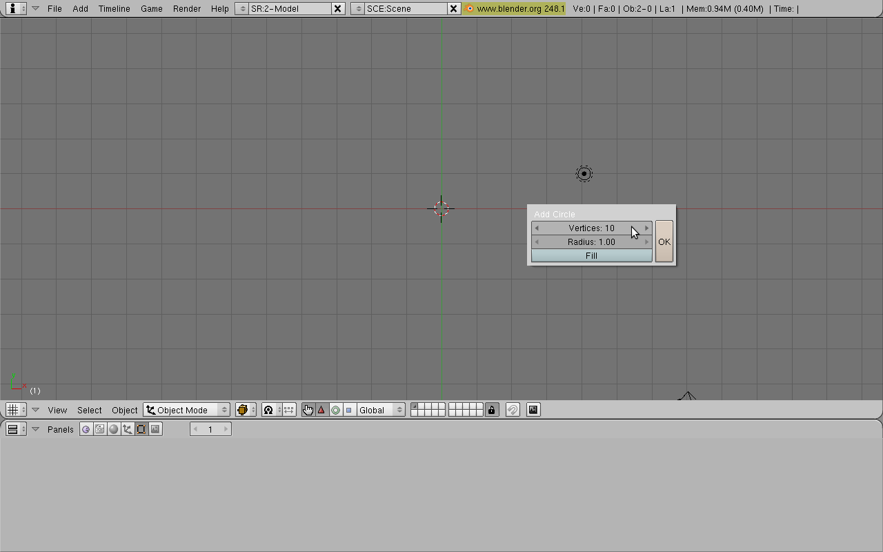
Next, we will extrude the vertices down. First enter side view by pressing Numpad 3 on your keyboard. As you can see, the circle is flat and not filled in. We will give it some depth. Switch to Edit Mode (TAB) and extrude the circle by pressing the E key and selecting "Only Edges". Move the mouse down and click to confirm the position (you may want to limit to Z axis by pressing the Z key).
::接下来,我们将向下挤出顶点.首先通过按键盘上的Numpad 3进入侧面视图.正如您所看到的,圆形是平的,而不是填充的.我们将给它一些深度.切换到编辑模式 (TAB) 并通过按E键和选择"仅边缘"挤出圆形.将鼠标向下移动并点击以确认位置 (您可能需要通过按Z键限制到Z轴).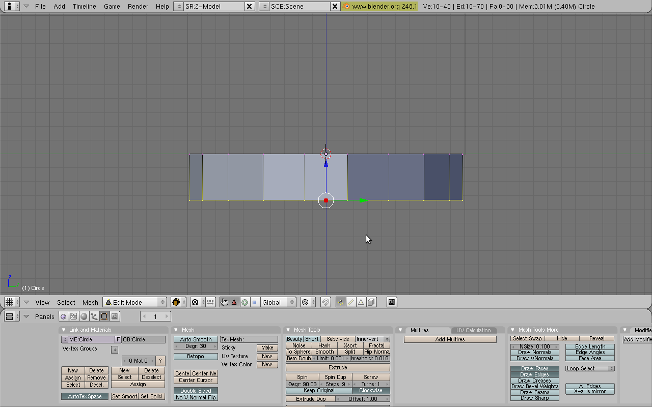
OK, what we just did is turn the circle into a hollow cylinder by extruding. But we don't want a cylinder. We want the bottom to be a nice tip. To do this, press Alt-M. This creates a Merging menu. Select "At Center". Now the bottom is a nice tip, like we want it!
::我们刚刚把圆圈变成一个空心圆柱体. 但是我们不需要圆柱体. 我们希望底部是一个漂亮的尖端. 要做到这一点,按 Alt-M. 这会创建一个合并菜单. 选择"在中心". 现在底部是一个漂亮的尖端,就像我们想要的那样!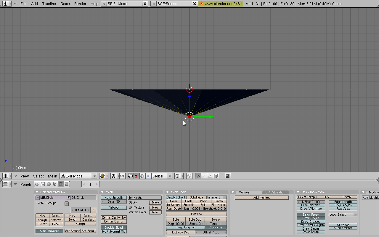
Now we will edit the top of the jewel. Press A to deselect everything and press the B key. This enters Box-Select Mode. Drag a box over the top vertices to select them.
::现在我们将编辑珠宝的顶部. 按A取消选项,然后按B键. 这进入了框选择模式. 拖动一个框在顶部的顶点上进行选择.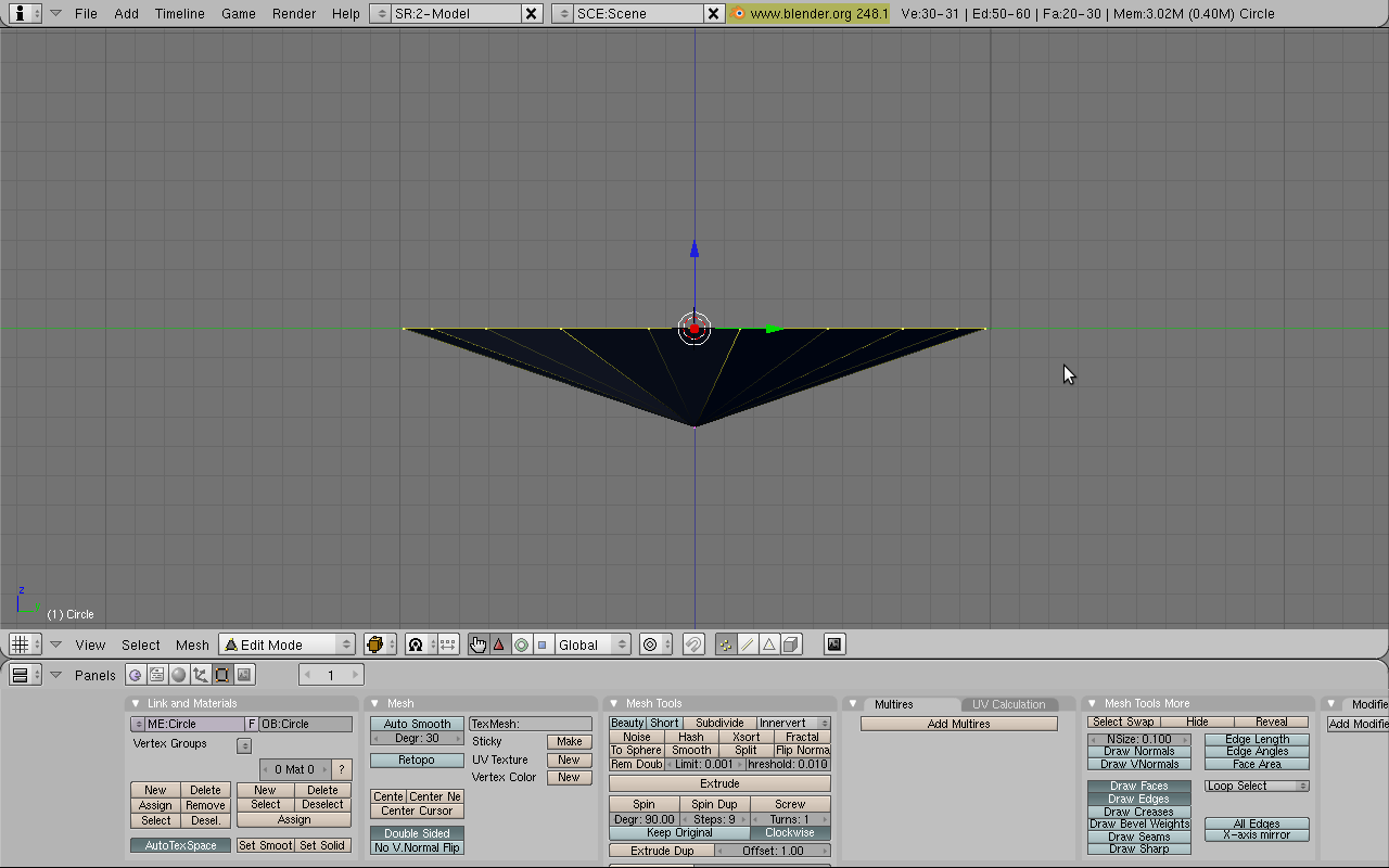
Now extrude the vertices upwards a bit (again: E key and "Only Edges"). Next, we will scale down these vertices to look a bit more like a jewel. Make sure the ring of vertices are selected and press the S key. This enters Scale Mode. Scale down the top vertices a bit and click to confirm.
::现在将顶点稍微向上挤出 (再次:E键和"只有边缘").接下来,我们将缩小这些顶点,使它们看起来更像一块宝石.确保顶点的环被选择并按S键.这进入了缩放模式.缩小顶点一点,然后点击确认.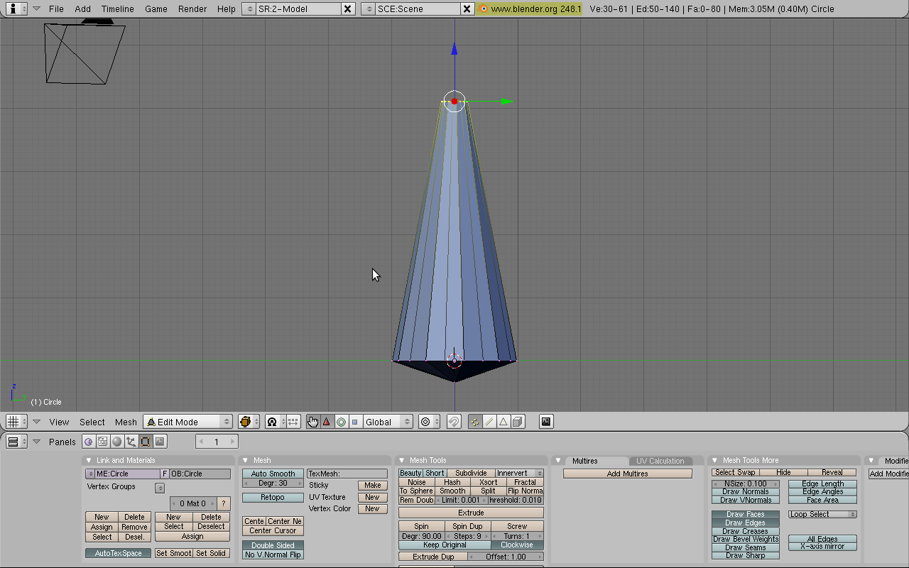
To look around your jewel model use the Middle Mouse Button or Alt-Left Click. Your jewel is looking fantastic! But there's a big gaping hole at the top. We'll fix that. First, enter side view (Numpad 3). Now extrude the topmost ring of vertices but don't move them anywhere with the mouse. If you are feeling doubtful, just press 0 and then Enter (or just click right mouse button). This makes a duplicate of rings placed over the original. Next merge this new ring with Alt-M -> At Center. This merges the duplicate ring, thus filling up your hole.
::为了查看你的珠宝模型,使用中鼠标按或 Alt-Left Click.你的珠宝看起来很棒!但顶部有一个大空洞.我们会修复它.首先,输入侧面视图 (Numpad 3).现在挤出顶端的环,但不要用鼠标移动它们.如果你感到疑惑,只需按0然后 Enter (或只需点击鼠标右键).这会使一个重复的环放置在原始的.接下来将这个新环与 Alt-M -> At Center合并.这将重复的环合并,从而填补你的洞.At last! Your jewel is finished! Feel free to rotate around it and make further adjustments if you are more advanced with using Blender.
::终于!你的宝石完成了!如果你使用混合器更先进,可以随意旋转它并进行进一步的调整.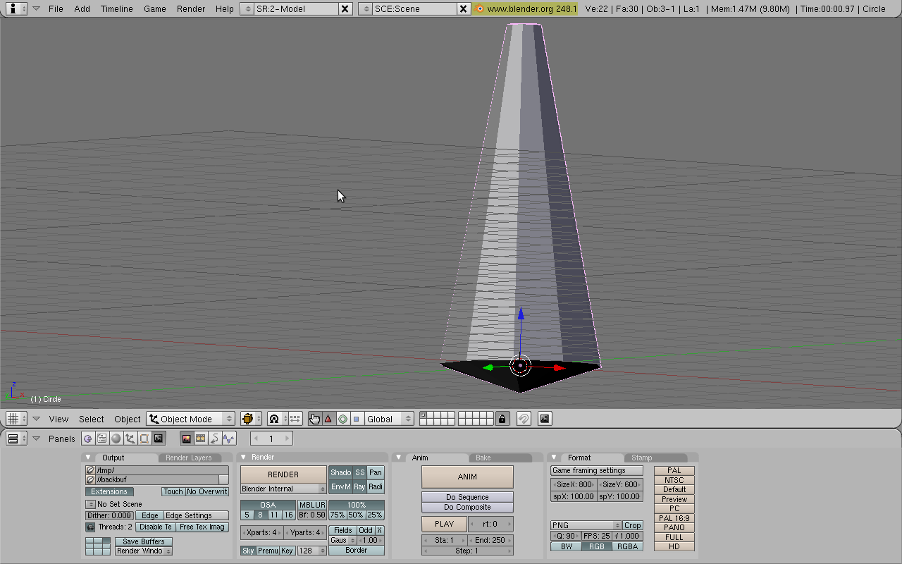
Shading
::遮阳Switch back to Object Mode (TAB) and show the Shading Panel (F5). Enable the Material Buttons (click on the button with a red ball). Add new material by clicking on "Add New" button in the "Links and Pipeline" tab. Copy the settings in the screenshot below. If you are having trouble setting the precise value to a slider, just click on the number. This allows a manual type-in. First, make it green by setting R to 0, G to 1, and B to 0. Next set the alpha slider to 0.458 (it looks like an A). Now press "Ray Mirror" (raytracing reflection) to turn it on and set it to 0.13. Now press "Ray Transparency" and set the IOR value to set 1.44. When you're done it should look like this:
::切换回对象模式 (TAB) 并显示遮光面板 (F5). 启用材料按 (点击红色球的按). 在"链接和管道"选项卡中点击"添加新"按添加新材料. 复制下面的截图中的设置. 如果您在设置滑块的精确值时遇到问题,只需点击该数字. 这允许手动输入. 首先,通过设置 R 为 0,G 为 1,B 为 0. 然后将alpha滑块设置为 0.458 (看起来像A). 现在按"射线镜像" (射线追踪反射) 打开并设置为 0.13. 按"射线透明度"然后将IOR值设置为 1.44. 当你完成时,它应该看起来像这样: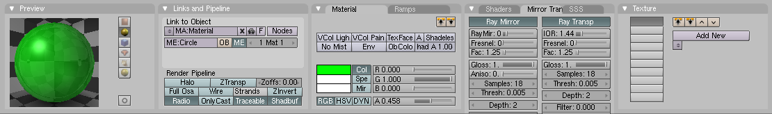
The finishing touch
::最后一个To improve the effect, add a plane underneath the jewel. In the Object Mode (TAB) press SPACE>>ADD>>MESH>>PLANE. Scale it 5 times using the S key. Then move it down a bit using the G key (press the Z key to restrict movement to the Z axis).
::为了提高效果,在珠宝下面添加一个平面.在对象模式 (TAB) 中按SPACE>>ADD>>MESH>>PLANE.使用S键缩放5次.然后使用G键向下移动一点 (按Z键限制移动到Z轴).You may try to render your jewel now. Press the F12 key. You may find that camera doesn't see whole jewel. Move and rotate the camera (using the G and R keys) to set it in the right position. You may want to switch to "Camera View" (Numpad 0) and try out "Camera Fly Mode" (SHIFT F). Try also moving the lamp and see what happens.
::您可以尝试现在染宝石. 按F12键. 您可能会发现摄像头看不到整个宝石. 移动和旋转摄像头 (使用G和R键) 设置到正确位置. 您可能想切换到"摄像头视图" (Numpad 0) 并尝试"摄像头飞行模式" (SHIFT F). 尝试移动灯,看看会发生什么.I've found that the jewel looks best with Ambient Occlusion on. So go to the Shading window, then the World buttons, click the Amb Occ tab and click the Ambient Occlusion button.
::我发现,如果使用环境遮蔽, 宝石的外观会更好. 所以,请进入"遮蔽"窗口,然后按"世界"按,Here is an example of what you can do:
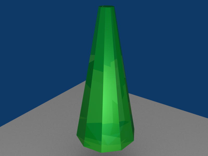
::以下是你可以做的事例:External links
::外部链接-
http://www.blender.org
::没有任何的 -
http://www.blenderartists.org
::通过一个新的平台,
-
http://www.blender.org
-
Modeling a picture
::模拟一个图片Ever seen an awesome looking picture you wanted to turn into a 3D model? Like a logo or a symbol? Well, it's actually pretty easy... it just takes some time to do.
::曾经看到一个看起来很棒的图片你想变成一个3D模型?像一个标志或象征?,它实际上很容易...它只是需要一些时间来做.-
First off, you're going to need a picture to trace. I'm currently doing a project for a friend to do with devils and demons, so I chose a demonic looking face for this tutorial:
Demonic Face
::首先,你需要一个图片来追踪. 我目前正在为朋友做一个与魔鬼和恶魔有关的项目,所以我选择了一个看起来像魔鬼的脸来做这个教程:魔鬼脸
-
Now open Blender and start a new project. Delete the default cube. Before you start tracing the face, you need to set the face as the background image. To do this, click 'view', then 'Background Image'. A box should pop up with only one button in it (Use Background Image), click it. Now some settings appear, we're only interested in one of them for this tutorial. Click the small button with a picture of a miniature folder on it (it looks kind of like a feather pen). It's the first one under the
Use Background Image
button. From there, select the picture you want to trace. Like this:
Background Selection
::现在打开Blender并开始一个新项目. 删除默认的立方体. 在开始跟踪脸之前,您需要将脸作为背景图像. 要做到这一点,点击'view',然后'Background Image'. 应该弹出一个盒子,其中只有一个按 (使用背景图像),点击它. 现在出现了一些设置,我们只对其中一个感兴趣. 点击小按,上面有一个迷你文件的图片 (看起来像羽毛笔). 这是使用背景图片按下的第一个. 从那里选择您想要跟踪的图片. 如下: 背景选择
-
OK, now for the long part. Zoom in to the new background image just a little bit. Now, add a Bézier curve, and size it down a little. Hit
F9
and, in
Curve Tools
, find and click the
Poly
button. Now there should be a few more vertices to work with and the curve should be just a bunch of joined lines. Select one point at a time and using the
GKEY
move it to a point along the background image(or face in this case). Do the same for all of the rest of the vertices, making sure you only have one vertex selected at a time or you'll move more than just the vertex you want to. Once this is done, select one of the end vertices of the curve (it doesn't matter which end) and use
SHIFT+DKEY
to copy that vertex. Move the newly copied vertex to a point along the edge of the face a small ways away from the vertex you copied it from. Continue doing this until you have a complete outline (of the whole face or just one part, like the ear). Here's what it should look like (I did the left ear):
Tracing
. You can't see it in the picture, but six of the points on the right side of the ear are connected, while the rest aren't. In order to get the effect we're looking for here, we need to connect all of the points around the edge to make an outline (make sure not to connect the points across the picture or you'll have a messed up outline).
::现在,长部分. 缩小到新的背景图像一点. 现在,添加一个贝齐尔曲线,并缩小它一点. 按F9,在曲线工具中,找到并点击Poly按. 现在应该有几个顶点来处理,曲线应该只是一堆连接的线条. 一次选择一个点,然后使用GKEY将其移动到背景图像的某个点 ((或面在这种情况下). 同样做所有其余的顶点,确保你只选择一个顶点,否则你会移动不仅仅是你想要的顶点. 完成后,选择曲线的某个终点 (不管是哪个终点) 并使用SHIFTDKEY+复制该顶点. 将新连接的顶点移动到沿着顶点边缘的一点,远离
(user note: hitting CTRL-LMB instead of SHIFT-DKEY will add a vertex that is already connected.)
:-
To get the outline for the whole face, just do exactly the same thing around all of the edges. We still have a problem though: most of the points aren't joined by a line, so all we have is a bunch of dots. This is easily solvable. Using the
BKEY
or the right click of the mouse, we select a bunch of vertices at a time (somewhere between 5 and 10), and hit the
FKEY
a few times. Every time you hit the
FKEY
it should connect two of the points. Do this until all of the selected points are connected, then deselect them and select another group and use
FKEY
to join them. Keep doing this until all of your points are connected. To connect the last two points, select all the points and press the
CKEY
, to close the polygon.
::为了得到整个面的轮,只要在所有边缘做完全相同的事情.我们仍然有一个问题:大多数点没有连接一条线,所以我们只有一堆点.这很容易解决.使用BKEY或鼠标的右键,我们一次选择一堆顶点 (在5到10之间),然后几次按FKEY.每次按FKEY时,它应该连接两个点.这样做直到所有选定的点连接起来,然后取消选择它们并选择另一个组并使用FKEY连接它们.继续这样做直到所有点连接起来.连接最后两个点,选择所有点并按CKEY,关闭多边形.
[edit: A better option would be to select a vertex on one of the ends of the whole line, hold down the CTRL and left-click on a certain point on the image. This will create a new vertex, immediately connected to the vertex you selected.]
::[编辑:更好的选择是选择整个行末端的一个顶点,按住CTRL键,然后左键单击图像中的某个点. 这将创建一个新的顶点,与您选择的顶点立即连接. ]-
Now that we've got the entire face traced (or outlined if you want to call it that), we can make it 3D. Hit
F9
again and find the Ext1 and Ext2 properties, shown here:
Ext1 & Ext2
. Change the values and see what happens. They correspond to the depth of the outline. Try changing them around until you find what looks good. Now, you'll notice that the lines just stick out straight. I'm still investigating how to actually model a head from the outlined face ... so if anyone has any ideas, feel free to add them to this page.
::现在我们已经把整个面部绘制出来了 (或者如果你想把它叫做轮),我们可以把它变成3D. 再按F9找出Ext1和Ext2的属性,如下图:Ext1和Ext2. 改变值,看看会发生什么.它们与轮的深度相对应. 试着改变它们,直到你找到看起来很好的东西. 现在,你会注意到线条只是直立出来. 我还在研究如何从轮面部中实际建模一个头部......所以如果有人有任何想法,请随时添加到这个页面上.
-
In order to make it have depth you should make the outline out of mesh points instead of a curve. Add a primitive mesh and delete all the vertices in edit mode, then ctrl click to all point outline. Add depth to the surface in a side view (split views so you can see what you're moving). It helps to have 2 or more reference images, but you can wing it. Usually the final result has to be subsurfed.
::为了使它有深度,你应该把轮从网点而不是曲线中制成.添加原始网格并删除编辑模式中的所有顶点,然后点击ctrl到所有点轮.在侧视图中添加表面的深度 (分割视图,这样你可以看到你在移动).有助于有2个或更多的参考图像,但你可以把它翼化.通常最终的结果必须被覆盖.
(USER EDIT: I accidentally started it with mesh instead of curve. You can do the same thing with extrude, but I have no idea how to go on after that) (USER EDIT LATER: If you subsurf it, it creates a relatively 3D looking image. Its really cool)
::现在,我可以使用一个模块,它可以在我的手上,我可以在我的手上,我可以在我的手上,我可以在我的手上,我可以在我的手上,我可以在我的手上,我可以在我的手上,我可以在我的手上,我可以在我的手上,我可以在我的手上,我可以在我的手上,我可以在我的手上,我可以在我的手上,我可以在我的手上,我可以在我的手上,我可以在我的手上,我可以在我的手上,我可以在我的手上,我可以在我的手上,我可以在我的手上,我可以在我的手上,我可以在我的手上,我可以在我的手上,我可以在我的手上,我可以在我的手上,我可以在我的手上,我可以在我的手上(Another user, even later: If you want to turn your curve into a mesh, hit Alt-C while in Object Mode. Note that this is NOT reversible.)
::另一个用户,甚至是后来:如果您想将曲线变成网格,请在对象模式中按 Alt-C. 请注意,这不是可逆的.(user edit: You can delete one vertex of a plane, in order to get a line. You may find easier to outline the picture extruding and moving points of the line you created.)
:(user edit: you can use this tracing technique to make solid and symmetric models, else, you would really have to use normal modelling)
::您可以使用这种追踪技术来制造固体和对称模型,否则,您将不得不使用正常建模.Printing a Rendered Image
::打印一个染图像Render your image. Exit or minimize the "Blender:Render" window. In blender, go to File -> Save Image... Then save your image. Then you can print it as you would print any other picture, using The Gimp, Paint, Microsoft's Photo Editor, or many others.
::染图像. 退出或缩小"混合器:染"窗口. 在混合器中,进入文件 -> 保存图像... 然后保存图像. 然后你可以打印它,就像你打印任何其他图像一样,使用Gimp,Paint,微软的照片编辑器,或许多其他.
-
First off, you're going to need a picture to trace. I'm currently doing a project for a friend to do with devils and demons, so I chose a demonic looking face for this tutorial:
Demonic Face
-
The Spin tool is a great tool for modeling objects you might make on a lathe quickly and easily.
::旋转工具是很好的工具, 可以快速轻松地在旋转机上制造物体.Lathe objects have circular cross sections along a certain axis. That is to say, when you cut such objects perpendicular to a certain axis you'll get circles. Examples of such objects includes rods, poles, wineglasses, and pails. A Blender render at the left shows some of these.
::轮对象沿着某个轴有圆形截面.也就是说,当你切割这些对象垂直于某个轴时,你会得到圆形.这些对象的例子包括杆,杆,酒杯和桶.左边的混合器呈现了其中的一些.With the Spin tool you only have to "model" half the outline of your object. The object is completed after you spin this outline. A bit of cleanup here and there and your model is finished.
::通过旋转工具,你只需要"建模"对象的一半的轮.在旋转轮后,对象就完成了.这里和那里有点清理,你的模型就完成了.
-
Wikimedia Commons requires that movies be uploaded as Ogg-Theora (OGG) files. As of Blender 2.42a, this is not a builtin feature of Blender. To get OGG files from your finished animation isn't difficult, though. However, you'll need additional software.
::维基媒体公众号要求电影作为OGG文件上传. 截至Blender 2.42a,这不是Blender的内置功能. 虽然从您的完成动画中获取OGG文件并不困难. 然而,您需要额外的软件.There are basically two ways to generate OGG files: you can use one of the many fine video editors or you can use special conversion programs. Video editors like LiVES or Cinerella allow you to load your AVI or your rendered frames, manipulate them, and create the OGG file from it. Please refer to the editor's documentation on how to achieve this.
::基本上有两种方法可以生成OGG文件:你可以使用许多优秀的视频编辑器之一,也可以使用特殊的转换程序.像LiVES或Cinerella这样的视频编辑器允许你加载AVI或染的,操作它们,并从中创建OGG文件.请参阅编辑器的文档,了解如何实现这一点.A disadvantage of a video editor is they are huge pieces of software, duplicating functionality that you already used when you created your animation file/s with blender. It's actually not necessary to install a video editor just for converting your animation to OGG Theora format.
::视频编辑器的一个缺点是它们是巨大的软件,重复了你用混合器创建动画文件时已经使用的功能. 实际上不需要安装视频编辑器,仅仅是为了将动画转换为OGG Theora格式.Converting saved frame picture files to Ogg Theora
::将保存的图像文件转换为Ogg TheoraIt's actually possible to convert frame pictures that you saved before to OGG format movies. The ffmpeg2theora software package , which is available in source or binary for all relevant systems, is capable of batch-processing files into an Ogg format movie. For example, if your frames were saved as PNG (with filenames filename001.png , filename002.png , etc.), you could convert them to a soundless OGG file with:
::实际上,您可以将之前保存的图片转换为OGG格式的电影. ffmpeg2theora软件包,可用于所有相关系统的源或二进制,能够将文件批处理成Ogg格式的电影.例如,如果您的以PNG格式保存 (具有文件名 filename001.png, filename002.png等),您可以将它们转换为无声OGG文件:ffmpeg2theora filename%03d.png -o output.ogv
Sound is possible too, as well as being able to set the quality and framerates. Consult the ffmpeg2theora documentation for more.
::音频也是可能的,以及能够设置质量和率.请参阅 ffmpeg2theora 文档以获取更多信息.Converting AVIs to Ogg Theora
::将AVI转换为Ogg Theoraffmpeg2theora can also convert AVI movies to OGG. Usage example:
::ffmpeg2theora也可以将AVI电影转换为OGG. 使用示例:ffmpeg2theora --optimize my.avi
-
This tutorial will guide you through how to make a simple animated Gif Using Blender and Gimp. This is useful for creating Avatars for forums etc. This tutorial assumes basic knowledge of blender and Gimp, see the basic animation tutorial .
::本教程将指导您如何使用混合剂和Gimp制作简单的动画Gif. 这对于创建论坛等的avatar很有用. 本教程假定Blender和Gimp的基本知识,请参阅基本动画教程.To start off you will need an animation, this usually should be no longer than 25 frames long.
::首先你需要一个动画,-
Open Blender. and delete the default cube and add a UV sphere, the default settings for the sphere work fine.
::删除默认立方体并添加紫外线球, 球的默认设置工作很好. -
Now set the camera size in the scene buttons (F10) to 50 by 50 (I am creating an avatar for deviant art where the required size is 50 by 50 pixels, you may change this if you want)
::现在设置摄像头大小在场景按 (F10) 50 50 (我创建一个虚拟身影的偏离艺术所需的大小是5050像素,你可以改变这个如果你想) -
set the frames to start at frame 1 and end at frame 20.
::设置从1开始到20结束. -
select the sphere and insert a LOC keyframe at frame 1 and 21, then go to frame 11, move the sphere and insert another LOC keyframe. this will create a looping animation.
::选择球体并在1和21插入一个LOC键框,然后进入11,移动球体并插入另一个LOC键框. 这将创建循环动画. -
Set the image type to PNG or JPEG (it doesn't matter) and render the animation.
::设置图像类型为PNG或JPEG (这并不重要),
Now to combine the images into an animated GIF using Gimp.
::现在使用Gimp将图像组合成动画GIF.-
Open the first image with gimp.
::打开第一个图像, -
Now click File-> open as Layer or press "Ctrl-Alt-O". Select the next frame and it will be added as a new layer. Repeat this for all of the images, or select all of the images by pressing "Ctrl-A".
::现在点击"文件-> 打开为层"或按"Ctrl-Alt-O". 选择下一个,它将被添加为一个新的层. 对于所有图像重复此操作,或按"Ctrl-A"选择所有图像. -
If you press Filters->Animation->Playback it should play the animation. It will probably have a low frame rate making it "choppy". this will be fixed in the next step.
::如果按下过器->动画->播放,它应该播放动画. 它可能会有低率使其"断片". 这将在下一步修复. -
Change the frame rate to 40 ms(25 frames per second). Choose file->Export as-> "Name".gif, then choose Save as Animation.
::选择文件->以"名称"导出->"gif",然后选择"以动画保存".
Note: Don't know wheter this is an additional feature of Gimp 2.6.8 or not, but i found out following: In Gimp 2.6.8, within the export wizard, you have to choose option: -save as animation- first and next at the option: -single picture where not mentioned- the option: one single picture per layer. -Sorry i use the german version of gimp-
::需要在下面的选项中选择: - 保存为动画 - 首先,然后在选项: - 没有提到的单图 - 选项:每层一个单图 - 抱歉,我使用了Gimp的德语版本 -You should end up with something like this:

::你应该得到这样的结果:Alternatively, you may try using addons to create animated Gifs directly from Blender. 2 options include Spritify and Bligify
::另外,您可以尝试使用附加功能直接从Blender创建动画Gif. 2种选择包括Spritify和Bligify
-
Open Blender. and delete the default cube and add a UV sphere, the default settings for the sphere work fine.
-
Overview
::概述This tutorial will guide you through the process of making 3D tiling backgrounds for use with web pages, your desktop, or anything else for that matter. We will be using Blender and a graphic editing program such as Adobe Photoshop or GIMP. I will provide detailed explanation to cator to beginners, however more experienced Blenderists can probably get away with just following the picture diagrams provided. You may also find the diagrams useful if English is not your native language, or if you hate reading instructions.
::本教程将引导您通过制作3D背景的过程,用于网页,桌面或其他任何东西.我们将使用Blender和图形编辑程序,如Adobe Photoshop或GIMP.我将为初学者提供详细的解释,但是更有经验的Blenderists可能只需遵循提供的图片图表就可以得到.如果英语不是您的母语,或者您不喜欢阅读说明,则图表也可能很有用.
Create The Object You Wish To Tile
::创建您想要的对象Start up Blender and look at your lonely cube. We will use this cube as a starting point for the sake of demonstration, but feel free to use any shape you like. Press " Tab " to enter Edit Mode . Press the " E " key on your keyboard and the Extrude menu will appear. Select " Individual Faces ". As you then drag your mouse cursor you will see some numbers move in the bottom left in the window and text saying "Shrink/Fatten". I recommend setting it to 1.0000 to keep it simple. Hold down the " Ctrl " key while dragging to do so in set increments.
::启动Blender,看看你的孤独立方体.我们将使用这个立方体作为一个起点,为了演示,但随意使用任何你喜欢的形状.按"Tab"进入编辑模式.按键盘上的"E"键,将会出现"挤出"菜单.选择"个体面孔".然后,当你拖动鼠标光标时,你会看到窗口左下方的一些数字移动,以及文字说"缩小/注意".我建议将其设置为1.0000以保持简单.在拖动时按住"Ctrl"键,以设置增量.Next, with the six faces of the cube still selected, press the " S " key to scale those faces. I recommend scaling to 0.8000.
::接下来,在立方体的六个面仍然被选择,按下"S"键来缩放这些面. 我建议缩放到0.8000.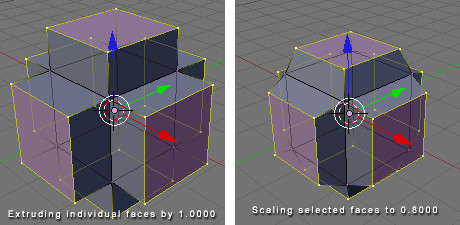
Good. Now that we have created our object we will prepare to tile it.
::好了. 现在我们已经创建了我们的对象, 我们将准备它.
Specify Your Tiling Area
::指定您的区" Tab " back into Object Mode and press " NumPad 7 " to go to the Top View, or manually click " View " at the bottom of the window and select " Top ".
::按下"NumPad 7"进入顶部视图, 或手动点击窗口底部的"View"并选择"Top".Press " spacebar " and from the menu that appears select " Add " > " Mesh " > " Plane ". The plane has appeared, but is obstructed by our cube object, so press " S " to scale the plane to 5.0000.
::按"空格条"从显示的菜单中选择"添加">"网格">"平面".平面已经出现,但被我们的立方体物体阻碍,所以按"S"将平面缩放到5.0000.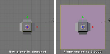
You'll notice that I've colored my plane black. This is only to make it easier for you to see. You need not bother with this as we will be deleting the face of this plane shortly.
::您会注意到我把飞机涂成黑色. 这只是为了让您更容易看到. 您不需要用这个来烦,因为我们将很快删除飞机的面部.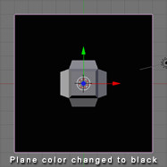
We now have an easily visible boundary representing the area which will be tiled. If at any point we decide we no longer need or want this we can move it to another layer by pressing " M " and selecting a layer to move it to.
::现在我们有一个很容易看到的边界代表的区域将被.如果在任何时候我们决定我们不再需要或想要这个我们可以将其移动到另一个层按"M"并选择一个层移动到.
Tile Away!
::没有!Now the fun part begins. If you have created 2D tiling backgrounds before, this concept will be very familiar to you.
::现在开始了有趣的部分. 如果你以前创建过二维背景,While in Object Mode , select your cube object. At this point you have a couple of options. One is to make duplicates of the cube object. Another is to make linked duplicates of the cube object. I recommend making linked duplicates because you can later edit the mesh of one object in order to change the mesh of all the duplicated objects. This can be especially useful if you later plan to animate your tiling background (careful not to distract from the foreground) . It is also useful if you want to experiment with new designs easily without having to re-place all your objects.
::在对象模式中,选择你的立方体对象.此时你有几个选项.一个是对立方体对象进行重复.另一个是对立方体对象进行链接重复.我建议做链接重复,因为你可以稍后编辑一个对象的网格,以更改所有重复对象的网格.这可能特别有用,如果您稍后计划动画您的背景 (小心不要从前景分心).如果您想轻松地尝试新的设计而不必重新放置所有对象,这也很有用.
With your cube object still selected, press " Alt+D " to make a linked duplicate. (Non-linked duplication is done with "Shift+D") Now hold down " Ctrl " to move in set increments and move the object to one of the corners of our plane. Make sure the center of the object (represented by a pink dot) is aligned with the very corner of the plane. At this point you may notice it's somewhat difficult to tell whether the center of the object is exactly on the corner of the plane, and that's why we are going to press " NumPad 5 " or click " View " and select " Orthographic ". For all practical purposes we can spend the rest of the time we are building the tiling pattern in Orthographic View because this view is essential for tiling.
::现在按下"Ctrl"按,以设定增量移动,并将对象移动到平面的角落之一. 确保对象的中心 (用粉红色点表示) 与平面的角落对齐. 在此时,您可能会注意到对象的中心是否正确地位于平面的角落,这就是为什么我们要按"NumPad 5"或点击"View"并选择"Orthographic". 为了所有实际目的,我们可以在Orthographic View中花费剩余的时间来构建板模式,因为这个视图对于板至关重要.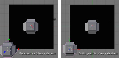
Now with your duplicate object still selected, scale it (" S " key) so that is somewhat smaller than the first. Then rotate it using the " R " key. While rotating you can constrain to a particular axis by typing " X ", " Y ", or " Z " respectively.
::现在,当您的重复对象仍然被选择时,请缩小它 (S键),使其比第一个小一些.然后使用"R"键旋转它.在旋转时,您可以通过分别输入"X"",Y"或"Z"来限制特定的轴.We will now make linked duplicates ( Alt+D ) of our rotated and scaled cube object and place one in each corner exactly on the grid (remember to hold " Ctrl " while dragging). If you place an object in one corner, you must place it in all four corners because corners touch both the X axis and the Y axis.
::现在我们将对旋转和缩放的立方体对象做出连接的复制 (Alt+D),并将一个在每个角落正确地放置在网格上 (记住在拖动时按住"Ctrl").如果您将对象放置在一个角落,您必须将其放置在所有四个角落,因为角落触及X轴和Y轴.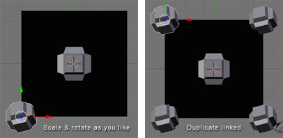
Now as you will notice in the following diagram, I made an object that is crossing over the edge of our plane. This is good. This is how to make natural tiling backgrounds. However! Whenever we do this we must be absolutely certain to do the same on the opposite side, or else our backgrounds will not tile properly.
::现在,正如你在下面的图中看到的,我做了一个物体,它穿过我们平面的边缘. 这很好. 这就是如何做自然的背景. 然而! 每当我们这样做我们必须绝对确定在相反的侧面做同样的事情,否则我们的背景不会正确地.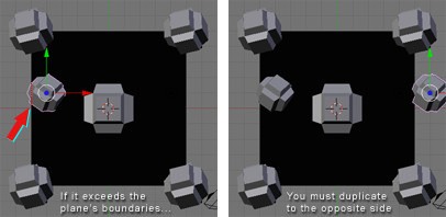
So now we've created a few objects of different sizes and orientations, however they have all been along the same spot on the Z axis. So let's give our pattern some depth - after all, that is the joy of working in 3D!
::现在我们已经创建了几种不同大小和方向的物体, 但它们都沿着Z轴的相同点. 让我们给我们的模式一些深度 - - 毕竟,这就是3D工作的乐趣!Before we do this, we'll want to get our guide plane out of the way. So right click on the plane to select it, then " Tab " into Edit Mode . Press " X " and from the Erase menu choose " Only Faces ". Now " Tab " back into Object Mode . There! We now have only the segments of the plane as our guide.
::在我们做之前,我们需要把导航平面从路上移除.所以右键点击平面来选择它,然后"Tab"进入编辑模式.按"X"从删除菜单选择"只需面孔".现在"Tab"回到对象模式.就这样!我们现在只有平面的部分作为我们的导航.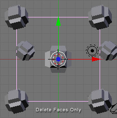
Hold down the middle mouse button while dragging the mouse to see what our design looks like in three dimensions. Now right click one of the cube objects, duplicate a linked copy ( Alt+D ), and press " Z " to constrain movement to the Z axis.
::按住鼠标中键,同时拖动鼠标,以查看我们的设计在三维中是什么样子. 现在右键单击一个立方体对象,复制一个链接的副本 (Alt+D),并按"Z"来限制移动到Z轴.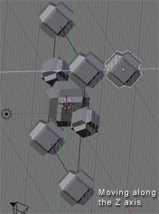
Navigate in this way along the X and Y axis as well and once you've found a good spot, scale and rotate . Remember to make a duplicate on the opposite side whenever you cross the outline of the plane guide. You can go on like this and populate your tiling pattern with as many objects as you wish. The grid is your friend during this process, so you should always have your finger on " Ctrl " while moving the duplicate of an object that crosses a border of the guide plane. Also, any object that will "tile" across the border must be at the same point on the Z axis as its counterpart on the other side of the seam. Press " NumPad 7 " periodically to see where you are from a 2D standpoint. This is the view from which we will eventually render the image, so this perspective is the one that counts. Beginners, remember that mouse wheel zooms in and out, and " Shift+middle mouse button " allows you to "drag" your way around.
::沿着X和Y轴这样导航,一旦找到一个好的位置,缩放和旋转.每次越过平面导图的轮时,请记住在对面做一个重复.你可以这样继续,并随心所欲填充你的形图案.在这个过程中,网格是你的朋友,所以你应该在移动一个穿过导图平面边界的对象的重复时,总是把手指放在"Ctrl"上.此外,任何将""跨越边界的对象必须在Z轴上的同一个点与其对应在接的另一边.定期按"NumPad 7"以查看你在哪里从2D角度.这是我们最终将视角染的视图,所以这是重要的视图.初学者,请记住鼠标轮放大和缩小,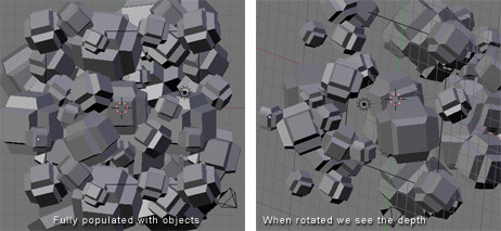
Keep in mind that in Orthographic View we do not perceive the depth of objects. Those far away and those near by appear to be at the same distance. This is what allows us to make a tiled image, but it also limits the apparent depth of the scene. We can compensate for this by scaling down the objects we want to appear further away. Or, as in this example, we can just make each object a different size and place some in front of others.
::记住,在正写视图中,我们看不到物体的深度.远处的物体和附近的物体看起来在相同的距离.这使我们能够制作形象,但也限制了场景的表面深度.我们可以通过缩小我们想要更远的地方出现的物体来弥补这一点.或者,像本例一样,我们可以让每个物体的尺寸不同,并将一些放在其他物体前面.
Camera Settings
::摄像机设置We will now position the camera directly over our cluster of objects. Press " NumPad 7 ", center the view on the cluster using " Shift+middle mouse button ", and zoom out a couple notches with the mouse wheel . From the 3D View Window' s menu, click " View " > " Align View " > " Align Active Camera to View ". Now you may be wondering why everything appears to be distorted. This is because when we changed to the camera's perspective, the view automatically reverted to Perspective View because by default the camera is set to that view. But just as we changed to Orthographic View in the 3D View Window, we can change the view of the camera as well. While in Object Mode , swivel the view until you see the camera. It is represented by a pyramidal wireframe with a black triangle atop the opening. Right click to select it. Now press " F9 " or click the Editing button (it's icon is four vertices joined in a square). Now in the Camera panel you will see a button labelled " Orthographic ". Press it. Above the button is a value labelled Scale . Set it to around 20. (See figure below)
::现在我们将把相机直接放置在对象集群上.按"NumPad 7",使用"Shift+中鼠标按"将视图放在集群的中心,并用鼠标轮缩小几.从3D视图窗口的菜单中,单击"View">"Align View">"Align Active Camera to View".现在你可能想知道为什么一切似乎被扭曲了.这是因为当我们更改到相机的视角时,视图自动返回视角视图,因为默认情况下相机设置为该视图.但正如我们在3D视图窗口中更改为正写视图,我们也可以更改相机的视图.在项目模式中,旋转视图按直到看到相机.它是由一个带有黑色三角形的金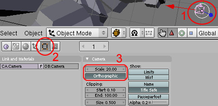
Lighting & Materials
::照明与材料Place some lights in your scene, and add some materials to your objects. Lighting and materials are subjects which demand their own tutorials, so if you don't know how to do these things yet, please consult the Wiki.
::照明和材料是需要自己教程的科目,所以如果你还不知道如何做这些事情,请咨询维基.Note: I advise lighting your scene pretty evenly in order to make the tiling seem contiguous.
::建议您照明场景的光线均, 以使看起来连续.Note: You could also only use Sun lamp, so the light is clean all over the mesh!
::需要注意的是, 您也可以使用太阳灯, 如此一来, 整个网格的光线都很清洁!
Rendering
::染Now that you've presumably got your lighting and materials as you want them, it's time to render the scene. Under User Preferences click " Render " > " Render Settings " or just press " F10 ". In the Format tab you can choose the dimensions of your rendered image, the file format you prefer, and the quality. I'm going with 800x600 at 100% quality.
::现在你可能已经得到了你想要的照明和材料,现在是时候染场景了. 在用户偏好下单击"染">"染设置"或只需按"F10". 在格式选项卡中,你可以选择染图像的尺寸,你喜欢的文件格式和质量. 我使用800x600的100%质量.
'Shopping
::购物And it's time to begin post-production. Open your rendered image in your preferred image editor. I will be using Photoshop in this example. Now find and mark the four corners of your tile (on a new layer of course). Just eyeball it.
::现在是开始后期制作的时候了. 在您喜欢的图像编辑器中打开您的染图像. 在这个例子中,我将使用Photoshop. 现在找到并标记您的的四个角 (当然在一个新的层上). 只是眼球它.
We will use guides to mark the tile boundaries. In Photoshop guides can be inserted by selecting " View " > " New Guide... ". Guides can be positioned with the Move Tool . You can zoom in and make sure your guides are accurately positioned by holding " Ctrl " while typing " + " or " - ". You can now hide or delete the layer with the markers, as that was only to help us get accurate guides.
::我们将使用指南来标记边界. 在Photoshop中,可以通过选择"查看">"新指南"...来插入指南. 通过移动工具可以定位指南. 您可以放大缩放,并通过按住"Ctrl"键键在键入"+"或"-"中确保您的指南的位置准确. 您现在可以隐藏或删除带有标记的层,因为这只是为了帮助我们获得准确的指南.Should you decide to make an animated tiling background I recommend layering all your frames on top of one another in your image editor before editing in order to keep the position uniform. You can then animate them using Adobe ImageReady (comes with Photoshop) or find decent low-budget and occasionally free GIF animation programs online.
::如果您决定制作动画的背景,我建议在编辑之前将所有相叠加在图像编辑器中,以保持位置均. 然后您可以使用Adobe ImageReady (附带Photoshop) 动画它们,或者在网上找到不错的低预算,偶尔免费的GIF动画程序.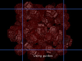
Now select an area just outside of the guides with the Marquee Tool . Make sure " Feather " is set to 0px and that the marquee is rectangular and Style is set to Normal (meaning no Fixed Aspect Ratio or Fixed Size). Also, it will help you to have Snap enabled, so go to " View " and make sure it is enabled for guides.
::现在使用标志工具选择指南外面的区域. 确保"羽毛"设置为0px,标志是矩形,样式设置为正常 (意味着没有固定比例或固定大小). 此外,它将帮助您启用Snap,所以去"查看"并确保它是启用指南.Once you have selected the area, copy ( Ctrl+C ) and paste ( Ctrl+V ). Then drag to the right using the Move Tool and that piece should snap to the inside of the rightmost vertical guide.
::选择了该区域, 复制 (Ctrl+C) 和粘贴 (Ctrl+V). 然后使用移动工具向右拖动,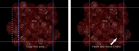
Select the Eraser Tool and choose a brush size. I'm going with a diameter of 65. You'll want to use a soft gradient-like brush for this. Now erase the left edge of the newly pasted selection so that it blends into the picture. Don't erase any of the right edge.
::选择"消光工具"并选择刷子大小. 我使用直径为 65. 您需要使用软的渐变式刷子来完成此操作. 现在,请擦除新粘贴的选择的左边缘,以便它融入图片中. 不要擦除任何右边缘.
Press " Ctrl+E " or alternatively, select " Layer " > " Merge Down ".
::按下"Ctrl+E"或选择"层">"合并".Alright, so that procedure you just performed copying from left to right - now do it bottom to top. Once again, erase the edge. Do a Save As .
::现在从下到上, 再一次, 擦掉边缘. 执行"保存为".Finally, select the square center area that will become your tile and do " Image " > " Crop ".
::选择一个正方形的中心区域, 选择"图像">"剪切".Now scale your new tiling background to a web-friendly size. Save As a JPEG, GIF, or PNG. You're done!
::现在将您的新背景缩小到一个网络友好的尺寸. 保存为JPEG,GIF或PNG. 完成了!Note:If your pattern still isn't tiling quite perfectly, load the version with the guides again and repeat the copy-paste-erase process. Remember to merge down your layers each time or the corners may not tile correctly. If still no joy, try tiling the background in a web browser, taking a screenshot, pasting that into your graphics editor, and touching up from there.
::注意:如果您的图案仍然不完全,请重新加载版本的指南并重复复制-粘贴-删除过程.请记住每次将您的层合并,否则角落可能不会正确地.如果仍然没有快乐,请尝试在Web浏览器中背景,截取屏幕截图,将其粘贴到图形编辑器中,然后从那里进行触摸.Here is the final result:
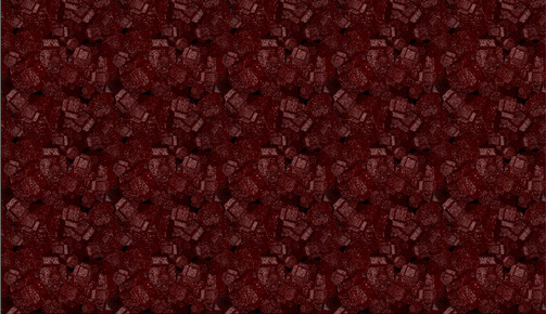
::结果如下:
-
Cool things in Blender that aren't that obvious. Useful tips and tricks in Blender.
::在Blender中不那么明显的酷东西. 在Blender中有用的技巧和技巧.Attribution
::归因Many of The Following Tips and Tricks have been contributed by members of the CGsociety.org , a Public Society for Digital Artists. The tips have been extracted from a CGsociety thread . They have been roughly edited to improve readability.
::以下许多技巧和技巧是由CGsociety.org的成员提供,CGsociety.org是数字艺术家的公共协会.这些技巧是从CGsociety的线程中提取的.它们已经大致编辑以提高可读性.File Browser Functions
::文件浏览器功能Delete, Move, Rename, and Make Directory
::删除,移动,更名,并创建目录When you are inside a file browser for loading or saving something and you want to create a new directory, just add the name to the path on top of the window and confirm 'Makedir'.
::您需要创建一个新目录, 仅需在窗口顶部的路径中添加名称并确认"Makedir".you can also delete(x), move(m), or rename
a file. you can do action on multiple files by seling with right click
::您还可以删除 (x),移动 (m) 或重命名Preview images when loading them as a texture
::预览图像当加载它们作为纹理Whenever you are loading images as a texture, you can hold down Ctrl while clicking on the 'load'
::任何时候你是装载图像作为质地,你可以按住Ctrl,同时点击'载'Trick for Creating Quick File Revisions
::创建快速文件修改的技巧After you have saved a blend file or an image you can then save it in progression that is:
::保存一个混合文件或图像后, 您可以按次序保存:car .blend. or car .JPG
::汽车.混合. 或汽车.JPGNext time do "Save As" then press the + (plus) key which will advance the blend file by 1 every time it's pressed. example: car .blend becomes car 1.blend. press again car 2.blend and so on.
::下次按下"保存为"然后按下+ (加) 键,每次按下它,将将混合文件推进1次. 例如: car.blend 变成 car 1.blend. 再按 car 2.blend 等等.The - (minus) key will subtract one. I've gotten into the habit of saving frequently. Yeah I know there is now the undo feature but I like this better because it gives you a history in case you need to back a few levels of a build. You get a saved version at the level you choose.
::我已经习惯了经常保存. 现在有撤销功能,但我更喜欢这个,因为它给你一个历史记录,以防你需要备份构建的几个级别. 你在选择的级别得到保存的版本.Note: Blender automatically detects the number... meaning it does not need to be in any position. For instance: If you have a file named 001starport.png or .blend or whatever, pressing the + (plus) key will automatically name it 002starport.png. If you want to name it starport1.png, it will change it to starport2.png.
::注意:Blender 能自动检测到数字...这意味着它不需要在任何位置.例如:如果您有一个名为 001starport.png 或 .blend 的文件,按下 + (加) 键将自动命名为 002starport.png.如果您想要命名为 starport1.png,它将更改为 starport2.png.Two rules: The filename has to have a number. It can be 0, or 1, or 3.141569.
::文件名必须包含一个数字. 它可以是0,或1,或3.141569.If the file number is a negative, pressing + (plus) key will increase the "magnitude" of the negative number. I may have used magnitude wrong, if so, I mean pressing the + (plus) key will make -0.04 drop to -0.05. The - (minus) key will bring you only to 0, and then it will start to eat itself up.
::如果文件号码是负数,按+ (加) 键会增加负数的"大小".我可能用错了大小,如果是这样,我的意思是按+ (加) 键会使-0.04下降到-0.05. - (减) 键只会带你到0,然后它会开始自食.Open Recent
::打开最近Control O
::控制OObject/Vertex Manipulation
::对象/顶点操纵Constrain Movement to one Axis or to a plane
::限制运动到一个轴或一个平面when moving objects/vertices or set of objects/vertices ( [G] key) if you move in the direction of the global X axis (Up/Down) and then press the MMB , movement will be constrained to only move in the X axis, or if you move the vertices in the direction of the Y axis and then press MMB it will be constrained to move only in the Y axis. The same is true of the Z axis.
::当移动对象/顶点或对象/顶点集时 ([G]键),如果您在全球X轴 (上/下) 的方向移动,然后按MMB,则运动将被限制在X轴上移动,或者如果您在Y轴的方向移动顶点,然后按MMB,则它将被限制在Y轴上移动. Z轴也是如此.You can achieve the same effect by using the X, Y or Z keys while in grab mode. You simply have to press X key, Y or Z, once to lock to X Y or Z global axis,*
::您可以通过使用X,Y或Z键在抓取模式中实现相同的效果.您只需按一次X键,Y或Z键,才能锁定到XY或Z全球轴,*To Constrain the Movement to two axes (a plane): Press Ctrl+X to move in the Z-Y-Plane. Ctrl+Z =XY, Ctrl+Y =XZ.*
::为了限制运动到两个轴 (一个平面):按Ctrl+X在Z-Y平面内移动.Ctrl+Z=XY,Ctrl+Y=XZ.*Alternatively, Select scaling mode and select the axis not to scale with the selecting button at the same time as you hit Shift .
::选择"选择缩放模式"并选择轴不缩放与选择按同时按下"转移".-
in every case You can hit the X,Y or Z button again to constrain movement to a different set of axes. Normally this different set of axes is local. However you can change the identity of this set to global, local, normal, or view by pressing
Alt+Space
. which cycles through the different identites.
::在每种情况下,您可以再次按下 X,Y 或 Z 按,以限制移动到不同的轴集.通常,这个不同的轴集是局部的.但是,您可以通过按 Alt+Space 来改变这个集的身份,将其变为全局,局部,正常或视图.
Note: All of these shortcuts work with scaling and Rotating as well
::注意: 所有这些快捷方式都能与缩放和旋转一起工作Shrink/fatten mesh in direction of vertex normals
::在顶点正常方向上缩小/增肥When you're mesh-editing, Alt+S will shrink/fatten the mesh selection in the direction of the vertex normals.
::在编辑网格时,Alt+S将在顶点的方向上缩小/加大网格选择.
Vertex Parenting
::顶层育儿You can parent object to a Mesh, in that case you are parenting to the center of the mesh.. BUT if the mesh is translated somehow (let's say by an armature' [S] pose) the center remains in the same spot, and thus the child object doesn't receive any transformation at all.
::你可以将父对象转移到网格的中心,但如果网格以某种方式转移 (比如说通过具的[S]姿势),中心就会保持在相同的位置,因此子对象根本不会接受任何转换.To solve this, you can parent the child object to a vertex (or a face) within the mesh, and any transformation that the vertex receives is passed to the child.
::为了解决这个问题,你可以将子对象与网格中的顶点 (或面) 关联,并且任何顶点所接收的转换都传递给子.There are only 2 options, to parent to any 3 vertex within the mesh or to parent to just one vertex. If you parent to 1 vertex then only location information is passed, with 3 vertex all transformations (rotation, location and size) are passed to the child.
::只有2种选择,在网格内对任意3个顶点进行父式或仅对一个顶点进行父式.如果您对1个顶点进行父式,则仅传递位置信息,在3个顶点中,所有转换 (旋转,位置和大小) 都会传递给子.How to do it? Starting in object mode select the child(ren), hold Shift and select the parent, enter edit mode, select one or three vertex, press Ctrl+P . That's it!
::如何做到?从对象模式开始选择子项 (child) 选择子项 (ren),按住Shift并选择父项,进入编辑模式,选择一个或三个顶点,按Ctrl+P. 完成了!Work around to welding Verts
::工作周围接的维尔特For Edge loop (Verts) position both loops together as close as possible then hit W then 4 (not on numkey pad). You can adjust how far the effect of collapse can go in the Edit window (a button on the right labeled Limit: ***, where * is a number).
::对于边缘循环 (Verts) 两条循环尽可能靠近,然后按W然后按4 (不按 numkey pad).您可以在编辑窗口中调整崩效果的范围 (右边的按标有Limit: ***,其中*是一个数字).As for individual Verts, e.g. Two vertices welded to become one, select both Verts, scale until they are very close then hit W then 4.
::两个顶点接成一个,选择两个顶点,缩放到它们非常接近,然后击W,然后击4.you can also do this with the snap combo
::您也可以使用快速组合来实现这一点select the vertex you want to weld together Ctrl+S , Cur -> Sel Ctrl+S , Sel -> Cur [W] , Remove Doubles
::选择要接在一起的顶点 Ctrl+S,Cur -> Sel Ctrl+S,Sel -> Cur [W],删除双重Also, whenever Blender pop up a menu with different options, you can just type in a number to choose one of the options (use the numbers not on the NumPad )
::另外,每当Blender弹出一个菜单与不同的选项,你可以只是输入一个数字选择其中一个选项 (使用数字不在NumPad)Make individual objects the camera and Change them back
::让单个对象的摄像机和改变他们回来If you select certain objects and press Ctrl+0(zero) it will make them the camera. I use it all the time to align spotlights.
::选择某些物体并按Ctrl+0将它们变成相机. 我经常用它来调整投光灯.Select your camera and hit Ctrl NumPad 0 to make it the active camera again
::选择你的相机,然后按Ctrl NumPad 0使它再次成为主动的相机Ordering Meshes in Vertex Groups
::在顶点组中排序网格If you are preparing to skin your meshes and you are ready to create the vertex groups, you should pay attention to the order in which you create them, because once they are created there is no way to re-arrange them on the vertex-group list.
::如果你准备去皮你的网格,你准备创建顶点组,你应该注意你创建它们的顺序,因为一旦他们创建没有办法重新安排它们在顶点组列表.That means that if you are a ultra-by-the-book person and you would like the vertex group alphabetically ordered on the list them you must create them in alphabetical order.
::如果你是个超级按照规则的人, 如果你想把顶点组按字母顺序排列在列表中,.. Or, if you would like them to be ordered according to their function (shoulders, then arms, then forearms, then palms, etc. you must create them in that order.
::或是,如果你想让它们按照它们的功能 (肩膀,然后是手臂,然后是前臂,然后是手掌等) 排序, 你必须按照这个顺序来创造它们.This may all sound like a stupid thing to care about, but If you have a character with 39 vertex groups you may quickly find that when one of them needs fixing it is a little difficult since they were randomly created.
::这听起来很愚蠢,但如果你有一个字符有39个顶点组, 你很快就会发现当其中一个需要修复时,Position and scale along face normal,
::面部的位置和尺度正常,- Shift V : Position camera along face normal, Alt S : scale selected vertices along face normal
::位置: 随着面部正常,Alt S: 随着面部正常的尺度选择的顶点
Using Fake Users
::使用假用户pressing Shift+F4 will turn the window into a ¨Data Select Window¨ where you can assign and unassign fake users to almost everything by selecting the name and pressing the F key
::按住Shift+F4将把窗口变成一个"数据选择窗口",你可以通过选择名称和按F键来将假用户分配和撤销几乎所有Creating a fake user allows you to keep useful data blocks (materials, textures, base meshes) at hand even if they are not linked to an object. You can use it to set a default material that would have the shader you like best.
::创建假用户允许你保持有用的数据块 (材料,纹理,基网),即使它们与对象没有联系.你可以使用它来设置一个默认的材料,它会有你最喜欢的遮光器.Align a selection of vertices on a plane
::在平面上对齐选择的顶点If you want to perfectly align a selection of vertices on a plane, you just have to follow these little steps:
::如果你想在平面上完美对齐一些顶点, 你只需要遵循这些小步骤:1.) Before you are selecting the vertices you want to align, position your 3D cursor in the plane that you want to align to (you could select the 4 vertices of a big plane and hit Shift+S / Cursor->Selection for example, but you can position it anywhere)
::1. 在选择要对齐的顶点之前,将3D光标放置在您要对齐的平面上 (例如,您可以选择一个大平面的4个顶点并点击Shift+S/Cursor->Selection,但您可以将其放置在任何地方)
2.) Now select those vertices you want to align
::2.) 现在选择那些顶点你想对齐3.) Choose "3D Cursor" under "Rotation/Scaling Pivot"
::3. 在"旋转/缩放轴"选项中选择"3D 标志符"4.) Now with the [S] -key start scaling mode, hit the key of the axis you want to move the vertices on (X,Y,Z)
::现在使用[S]键开始缩放模式,按键的轴,你想移动的顶点 (X,Y,Z)5.) Holding down the Ctrl-Key , you can now move the vertices in one line towards the cursor, until the value for the chosen axis is 0.000. Alternatively, just enter, using the keyboard, the scale factor you want (0 in this case) .
::现在可以按住Ctrl键,将顶点一行向着光标移动,直到所选轴的值为0.000. 另一个选择,只需使用键盘输入您想要的比例系数 (在这种情况下为0).6.) Hit LMB. The vertices are perfectly aligned along a plane through the 3D cursor.
::顶点在3D光标的平面上完美排列.This even works very well while in perspective view mode, so you can align on the fly and don't have to switch to front/side/top view all the time.
::您可以在飞行时对齐, 不必一直切换到前/侧/顶视图.Welding Vertices
::接顶部You can weld vertices by selecting them in edit mode and pressing Alt+M .
::您可以在编辑模式中选择并按 Alt+M 键接顶点.
View wireframe of hidden Verts
::查看隐藏的绿色的线框to view the wireframe of hidden Verts, make sure you are in WIREFRAME MODE and then turn SubSurf on and change the level to 0 If you already knew about this then
::确保您在WIREFRAME模式,然后打开SubSurf并将水平更改为0Select a true loop
::选择一个true循环shortcut is Shift + Alt + right Button of the mouse, serves to select true loop, in vertices as in edges like in faces.
::选择一个真循环, 在顶点和边缘, 像面孔一样.Selecting one object from a single mesh comprised of multiple objects
::从一个由多个对象组成的单一网格中选择一个对象If you have more than in Edit Mode, you can place your mouse cursor next to one of the Verts in the desired object, then press the "L" key to select all of the Verts linked to that one. "Alt+L" reselects in the same manner.
::如果您有超过一个在编辑模式下,您可以将鼠标标 cursor 放置在所需对象中的一个Verts旁边,然后按"L"键选择与该对象相关的所有Verts. "Alt+L"以同样的方式重新选择.Precise Zoom and Select/Deselect
::精确缩放和选择/删除Selecting: If you Hold down the Ctrl+LMB (left mouse button) and drag the mouse, it will allow you draw a selection as opposed to using the B button which gives you a square.
::选择:如果按住Ctrl+LMB (鼠标左键) 并拖动鼠标, 它将允许你绘制一个选择, 而不是使用B按给你一个方形.Deselecting:To draw an area to deselect, Hold down the Ctrl+ Shift+ LMB (left mouse button) and drag the mouse,
::删除选项:要画一个要删除的区域,按住Ctrl+Shift+LMB (鼠标左键) 并拖动鼠标,Zooming:Hold down the Ctrl+MMB . Move your mouse vertically to can get a more controlled zoom versus scrolling the Mouse wheel.
::放大:按住Ctrl+MMB键. 将鼠标垂直移动可以获得更可控的放大与滑鼠轮滚动.This feature may not be present in 2.37 or earlier versions.
::这一功能可能不在2.37或更早版本中.
Mouse Gestures
::鼠标的手势Left click and draw:
::按左键并画:-
a straight line - moves the selected object.
::一条直线 - 移动所选对象. -
a circle - rotates the selected object (note: this must be drawn fairly circle-like).
::一个圆 - 旋转选定的对象 (注意:必须绘制相当圆形). -
a V - scales the selected object.
::选择的对象的尺寸.
Selecting Obscured or Hidden Objects
::选择隐藏或隐藏的对象Say you are in front or side view and you want to select an object, but it is obscured or hidden behind other objects. If you press Alt RMB over a group of objects, a menu will be displayed in the 3D window allowing you to pick the object you wish to select.
::假设您在前方或侧面视图中,并希望选择一个对象,但它被遮蔽或隐藏在其他对象后面.如果您在一个对象组上按 Alt RMB,将在3D窗口中显示菜单,允许您选择您想要选择的对象.Select or Deselect Multiple Vertices
::选择或取消多个顶点的选择In Edit mode, when you click the RMB near a vertex that vertex (face or edge)will be selected, RMB again will reselect. By holding the Shift key this will allow you to add each selected vertex (face or edge) in that highlighted group.
::在编辑模式下,当你点击顶点附近的RMB时,该顶点 (面或边) 将被选择,RMB将再次重新选择.通过按住Shift键,这将允许你在该突出显示的组中添加每个选定的顶点 (面或边).Pressing the U key (Undo in Edit mode) will also remove the last selection you made.
::按下U键 (在编辑模式下取消) 也会删除您最近的选择.Alternatively, you can Press B and then draw a box with MMB . Anything caught in the box will be deselected. Also works with BB and the draw selection. Draw with MMB and you reselect.
::另一个选择是按下 B,然后用 MMB 画一个框. 任何被抓到的框都会被取消选项. 也可以使用 BB 和抽取选项. 用 MMB 画,然后重新选择.
Selecting multiple items
::选择多个项目You can hold Shift and use right mouse button to select multiple items to append.
::您可以按住Shift,然后使用鼠标右键选择多个要添加的项目.Measuring, length, distance on an object.
::测量一个物体的长度和距离.Hit "F9" (editing), you should have split (2) windows. One "3d" the other "buttons" go to the Mesh Tools 1 panel and press the Edge Length, Edge Angles and the dimensions will appear on your selections in the 3d view.
::按下"F9" (编辑),你应该有分开的 (2) 窗口. 一个 "3d" 其他"按"去网格工具 1 面板,按边长,边角和尺寸将出现在您的选择在3d视图.Adding Connected Vertices
::添加连接的顶点In Edit Mode, if only one vertex is selected, pressing "E" will add a vertex, on a freely defined place, connected to the selected one. As will holding CTR L and left clicking the mouse where you want the new vertex to be positioned.
::在编辑模式中,如果只选择一个顶点,按"E"将在自由定义的位置添加一个顶点,与所选的连接. 按住CTRL和左键鼠标将新顶点定位到您想要的位置.Note: It must be an Image texture and in wireframe mode to be visible.
::注意:它必须是图像纹理,并且在线框模式中可见.(2.37a)
::其他
Recalculate Normals
::重新计算正常值Ctrl + N = Recalculate normals outside (you might have to select faces before doing so) Shift + Ctrl + N = Recalculate normals inside
::Ctrl + N = 在外面重新计算正常值 (您可能需要在此之前选择面孔) 转移 + Ctrl + N = 在内计算正常值These two hotkeys are useful when you extrude some edges and see a kind of seam in between (due to normals pointing in different directions).
::两键在挤出边缘时很有用, 看到边缘之间有某种接 (因为正常的边缘指向不同的方向).Then, after selecting an edge, Ctrl + NumPad(+) selects the face associated with this edge. Ctrl + NumPad(-) deselect the face.
::然后,在选择边缘后,Ctrl + NumPad(+) 选择与边缘相关的面.Ctrl + NumPad(-) 取消面.
Create a Quad from two Tris
::从两个Tris创建一个四角形Alt + J when having two Tris selected makes a Quad.
::选择两个Tris时,Alt+J会产生一个四角形.Remove Doubles
::删除复制品To Remove Doubles use hotKey: W. You can adjust the "limit" option so that "Remove Doubles" has more or less tolerance. This option is located in editing window under the mesh tools panel, (i.e. weld vertices that are further?)
::要删除双重使用 hotKey: W. 您可以调整"限制"选项,使"删除双重"具有或多或少的宽容. 这个选项位于编辑窗口下面的网格工具面板, (即接顶点更远?)Combine edit levels on a mesh.
::在网格上结合编辑级别.When in Edit mode for a mesh (TAB key) you can choose the level that you wish to edit at. At the bottom of the 3D window, there are four buttons. Vertex, edge, face & back-face cull.
::在网格的编辑模式 (TAB键) 中,您可以选择您想要编辑的水平.在3D窗口的底部,有四个按.顶部,边缘,面部和背面的选.By default the vertex level is selected, if you hold Shift and press the edge button, you can use both at once.
::默认选择顶点水平,如果按住Shift并按边缘按,
Change Select Mode
::改变选择模式to change select mode (vertex, edge or face) you can press Ctrl+Tab . But this way you can't use the Ctrl+Key to ADD the select modes.. Still could be useful, if you don't have a header for the window you're working in..
::为了更改选择模式 (顶部,边缘或面部),您可以按Ctrl+Tab. 但这样您就无法使用Ctrl+Key添加选择模式. 如果您没有为正在工作的窗口设置头部,这仍然很有用.Precision Warping
::精确的扭曲When using the warp tool ( Shift+W ) you may find that there are times when you have trouble perfectly closing a 360-degree loop. This is because Blender will warp based on the total width of the selection, which may not necessarily be what you want.
::使用曲线工具 (Shift+W) 时,您可能会发现有时您无法完美关闭360度循环.这是因为Blender将根据选择的总宽度曲线,这可能不一定是您想要的.
Getting around this is simple, just select two verts to denote the new endpoints, duplicate them ( Shift+D ), scale the two verts times two, so they are just twice as far apart. Then select what you want to warp plus those two marker verts, and warp 720 degrees.
::绕过这个问题很简单,只要选择两个顶点来表示新的终点,复制它们 (Shift+D),缩放两个顶点乘以2,这样它们就相距两倍. 然后选择你想要曲的东西加上两个标记顶点,然后曲720度.
When done, click a vert on your mesh and type L to select everything linked to it. Then type H to hide it. Once you've hidden all of your mesh, all that remains are the two marker verts. Do a Select All ( A ) and type X to delete them. Now unhide your mesh using Alt+H and you have just the warped mesh, extra guide verts are all cleaned up.
::完成后,点击网格上的一个角点,输入L来选择与之相关的一切.然后输入H来隐藏它.一旦你隐藏了所有的网格,剩下的就是两个标记角点.做一个选择所有 (A) 和输入X来删除它们.现在用Alt+H来揭开你的网格,你只剩下扭曲的网格,额外的导向角点都被清理掉了.Precision Cutting
::精确切割The Knife Tool can actually be quite precise if you take advantage of the snap feature. Press K , choose "Knife(Exact)" and then hold the Ctrl key while choosing where you wish to cut and you will find that the path to be cut will now snap to nearby vertices.
::刀工具实际上可以非常精确,如果你利用快速切割功能.按K,选择"Knife (精确) "然后按住Ctrl键,同时选择你想要切割的地方,你会发现切割的路径现在会快速切割到附近的顶点.
Keep in mind that the vertices being snapped to don't have to be the ones you are cutting. Say you want to cut the midsection out of a UV sphere and you want the cut to be two grid units in height. While viewing the side of the sphere, add a plane, and scale it to be two grid units tall, and wide enough so that it extends beyond the sphere. Now select the vertices of the sphere (because what we have selected is what gets cut) and when you cut it, snap to the four verts of the plane. Now hit Enter to apply your perfect cut.
::记住,被切割的顶点不一定是你正在切割的.假设你想切割紫外线球的中部,并且你希望切割高2个网格单位.在查看球的侧面时,添加一个平面,并缩小它为2个网格单位高,并且足够宽,以便它延伸到球之外.现在选择球的顶点 (因为我们所选择的是被切割的东西),当你切割它时,切割到平面的四个顶点.现在点击Enter应用你的完美切割.
Using guide geometry such as a plane to cut other geometry "cookie-cutter" style can be extremely useful when accuracy is needed. Remember to align your view before cutting, since your view will determine the angle from which the geometry is cut.
::使用导向几何如平面切割其他几何"饼干切割机"风格,可以是非常有用的,当需要精度.记住,在切割之前,把你的视图,因为你的视图将决定从哪个角度切割几何.Working with Meshes
::用网格工作Turning Sub-Surfed Mesh into Normal Mesh
::将低冲浪网转换为正常网If you have a sub-surfed mesh you can turn THAT sub-surf mesh into a normal mesh. Just select the sub-surfed mesh and press Alt+C (Conversion).
::如果您有一个被潜入的网格,您可以将该被潜入的网格转换为正常网格.只需选择被潜入的网格,然后按 Alt+C (转换).How to remove (numb) black spots on a Mesh
::如何去除网格上的 (麻木) 黑点If a Sub-Surfed mesh becomes (numb) black on some places, that's because of the normals. Select all and press Ctrl+n and then confirm. now it should look prettier!
::如果一个Sub-Surfed网格变得 () 黑在某些地方,这是因为正常. 选择所有,然后按Ctrl+n,然后确认. 现在它应该看起来更漂亮!if the above solution does not work , save your Blend file, Quit Blender then restart. Use Ctrl O to open the last file and your mesh will have returned to correct shaded state.
::如果上述解决方案不起作用,请保存您的混合文件,退出混合程序,然后重新启动. 使用Ctrl O打开最后一个文件,您的网格将恢复到正确的阴影状态.Select all holes in a mesh and fill them
::选择一个网格的所有洞,并填补它们Shift+M * selects all Non-manifold edges/vertices (holes) in a mesh **. Then all you have to do is hit Ctrl+F to auto-fill those holes with "beauty fill".
::选择所有非多重边/顶点 (洞) 在网格**. 然后你只需要按Ctrl+F,以"美丽填充"自动填充这些洞.Shift+M is an alternative shortcut for 'Select Non-manifold'. You'll find this in the select menu when in mesh edit mode. The listed short cut there is Ctrl+Alt+Shift+M . Shift M is obviously a lot more comfortable on the fingers though!
::转换+M 是'选择非多重组'的替代快捷方式.当您处于网格编辑模式时,您将在选择菜单中找到此快捷方式. 列出的快捷方式是Ctrl+Alt+Shift+M. 转换M显然对手指更舒适!Although 'Non-manifold' usually refers to holes in your mesh, it is not necessarily only holes e.g., an edge with three faces coming out of it is also a non-manifold edge!
::虽然"非多面"通常指的是网格上的孔,但它不一定是只有孔,例如,一个边缘有三个面出来的边缘也是一个非多面边缘!
Fill in four or fewer vertices
::填写四个或更少的顶点Select the vertices and press [F] , this will fill in the empty space around them.
::选择顶点并按F, 这将填充它们周围的空白空间.To clean up a filled in space, select all the vertices for the area, and press [F] . Choose OK to make FCon. For example: add a plane in wireframe mode, extrude it several times, select all vertexes, then hit [F] .
::要清理一个填充的空间,选择该区域的所有顶点,然后按F.选择OK以使FCon.例如:在线框模式中添加一个平面,将其挤出几次,选择所有顶点,然后按F.
Animation
::动画Animation Preview in all windows at the same time
::在所有窗口同时预览动画It is well known that Alt+ a is for previewing an animation on the 3D window. But that's not all of it. Divide your screen into multiple 3D Windows, each from a different point of view.
::众所周知,Alt+a是用于在3D窗口上预览动画. 但这还不是全部. 将屏幕分成多个3D窗口,每个窗口都从不同的角度.Press Alt + Shift + a
::按下Alt+Shift+aEnjoy!!!
::享受吧!If you have an Action/Ipo Window and 3D windows open, and you issue the Alt + Shift + a command from the Action (or the Ipo) window, it will animate both (the action and the 3D) in sync!! Great for visualization of Ipo's effect on your model.
::如果您有动作/IPO窗口和3D窗口打开,并从动作 (或IPO) 窗口发出Alt+Shift+命令,它将同时动画 (动作和3D) !! 很好用于对您的模型Ipo的影响的可视化.Choose animation mode, Convert mouse movements to IPO
::选择动画模式, 将鼠标移动转换为IPO-T in IPO window: Choose animation mode, i.e., linear, bezier, constant - [R] in IPO window: Record mouse movements, and convert to IPO
::在IPO窗口:选择动画模式,即线性,贝齐尔,恒定的 -[R]在IPO窗口:记录鼠标移动,并转换为IPO
Animate procedural textures
::动画程序纹理To animate procedural textures, press 'i' with the mouse pointer in the materials window, and select the type of Key-Frame you wish to set in the pop up menu. advance a few frames, tweak your materials, and set another key frame.
::按下"i"按,然后在弹出的菜单中选择要设置的键框类型. 提前几,调整你的材料,并设置另一个键框.UV Mapping, Particles and Texturing
::紫外线映射,粒子和纹理Blender color picker
::混合器的颜色选择器Blender has a PhotoShop-esque color picker. Simply click on the color preview next to the sliders to use it. Hit enter when you have the color you want.
::混合器有一个PhotoShop-esque的颜色选择器. 单击滑块旁边的颜色预览器使用它. 当你有你想要的颜色时,按Enter.
Saving your face groups selections
::保存您的面部组的选择Regarding UV mapping and Face Groups Selections there seems to be the general misconception that you can't save your face groups selections on Blender.
::似乎有一个普遍的误解,即你不能在Blender上保存你的面部组选.Most people already know that from within the Face Select Mode (Potato Mode) you can switch into Edit Mode and whatever selection you do while in Edit Mode is passed back to Face Select Mode when you exit the Edit Mode.
::大多数人已经知道,从面部选择模式 (土豆模式) 中,你可以切换到编辑模式,无论在编辑模式中做什么选择,Well, Did you ever wonder why Material Index Groups (that are nothing more than face groups with a common material on them) have those little 'Select' and ´Deselect' buttons there? Sure they come handy for later modification of the material index but that is not all about them.
::您有没有想过为什么材料索引组 (它们只是面部组,上面有共同的材料) 有那些小的'选择'和'删除'按吗?当然,它们对于后期修改材料索引很有用,但这并不是全部.Do this: Before starting the UV unwrapping job, cut your mesh by creating as many material indexes as you need, you can even assign each one a different color so you can be sure that there is no face orphan. Once you have the mesh all cut and sliced (so to speak) you enter in Face Select Mode, then switch into Edit Mode, select the index containing the faces you want to unwrap, press 'Select', leave Edit Mode and Voile! You now have an entirely useful face group waiting for you to unwrap. No more manual (and imprecise) face selection is needed.
::切开网格之前,先创建尽可能多的材料索引,甚至可以给每一个网格分配不同的颜色,这样你就可以确定没有面孔孤儿.一旦网格全部切割和切割 (可以这么说),你进入面孔选择模式,然后切换到编辑模式,选择包含你想解开的面孔的索引,按'选择',离开编辑模式和Voile!你现在有一个完全有用的面孔组等待你解开.不再需要手动 (和不精确) 的面孔选择.If you later need to change the mapping of those faces, don't fear. Just make sure there isn't any face selected on Potato Mode, do as you did first (enter edit mode, select the index, exit edit mode) and there are your very same faces selected again with the UV mapping you already assigned to them.
::如果您后来需要更改这些面孔的映射,不要担心. 只要确保在"土豆模式"中没有任何面孔被选中,就像您先前所做的那样 (进入编辑模式,选择索引,退出编辑模式) 并且您的相同面孔再次被选中,您已经分配给它们的紫外线映射.Note: Another benefit of have precise face selection groups is that, initially, you don't have to worry about UV coordinates overlapping, since you know have the way to select ONLY the faces you want to. For example, you unwrap all your faces by groups and when you are done you can start thinking about scale and position within the texture map, not like before when you have to solve those things as you go.
::注意: 精确的面部选择组的另一个好处是,最初,你不必担心紫外线坐标重叠,因为你知道有办法选择你想要的面部.例如,你把所有面部分成组,当你完成时,你可以开始考虑在纹理图中的规模和位置,而不是像以前一样,你必须在进行时解决这些事情.
Bulk Texture Change
::总体质感变化Consider a scenario in which you have a scene with a 100 mesh objects, and 50 of them have one texture and 50 of them have another.
::50个有某种纹理,而50个有另一种.If you want to change the texture of the first 50, but don't want to change each individually, do the following. Add a Plane out of the view of the camera. Add your new texture (Material) to the plane. Then use the “Copy to material Buffer” button in the header of the Material buttons. Select one mesh object of the same sort that you want to change, open Material buttons and Paste from Material Buffer.
::如果您想更改前50个图像的纹理,但不想单独更改每一个图像,请执行以下操作. 在摄像头视图中添加一个平面. 将您的新纹理 (材料) 添加到平面中. 然后在材料按的头部使用"复制到材料缓冲区"按. 选择您想要更改的同一类型的一个网格对象,打开"材料按",然后从材料缓冲区粘贴.All the mesh objects with the same texture will now have the new texture.
::所有具有相同质感的网格对象现在将具有新的质感.Alternatively, If you have a material that you want to apply to a lot of objects at once:
::另一种方法是,如果您有材料,并希望同时将其应用于许多物体:1. Select all the objects you want to apply the material to. 2. Apply a material. (this only applies to the last selected object) 3. press Ctrl+L > Materials. (this links the material of the last selected object to all the other objects)
::1. 选择所有想要应用材料的对象. 2. 应用材料. (这只适用于最后一个选择的对象) 3. 按Ctrl+L > 材料. (这将最后一个选择的对象的材料与所有其他对象联系起来)
Negative Meta-Balls
::负的元球Add>Metaball as usual. Exit EDIT mode and Add>Metaball. This time before you exit EDIT mode, hit the Negative button in the EDIT buttons window. Then leave edit mode.
::添加> 转换球 (Metaball) 按常规. 退出编辑模式,然后添加> 转换球. 在退出编辑模式之前,请在编辑按窗口中按消极按. 然后离开编辑模式.If you move the negative Metaball around, you can see the effect it has on the positive metaball.
::您可以看到它对正能量代谢球的影响.Be careful though, as negative metaballs are not displayed in the same manner as positive metaballs, you will only see the Pivot point not a meta-mesh.
::由于负代谢球与正代谢球的显示方式不同,所以你只能看到旋转点,而不是元网.This is a little test you can try to see the amazing effects negative metaballs can produce.
::这是一个小测试, 您可以尝试看出负代谢球能产生多么惊人的效果.Make 1 Metaball, make it big. Place three spheres (UV) inside, make them emit particles, one 100, one 200, one 300 particles. Parent three negative metaballs, one to each sphere, and use dupli-vert on each sphere. Make the 100 duplicate metaball quite big, the 200 medium and the 300 small. Hit Alt A to run animation in 3D window.
::制作一个元球,使其大.将三个球 (UV) 放置在里面,使它们发射粒子,一个100个,一个200个,一个300个.将三个负元球,一个给每个球,并使用每个球上的重复绿色.使100个重复元球相当大,200个中等和300个小.按 Alt A 在3D窗口中运行动画.(Click here for this author's negative-metaball AVI.)
:Maintain the UV layout when moving/scaling/rotating UV co-ords.
::在移动/缩放/旋转UV坐标时保持UV布局.When you have the UV image/editor window open and have loaded an image you want to UV map to a mesh, click on the UV tab in the header bar and turn off 'Snap UV to pixels'.
::打开UV图像/编辑器窗口,并加载您想要将UV图像映射到网格时,请点击头条中的UV选项卡并关闭"将UV图像映射到像素".This will help to maintain the UV layout when moving/scaling/rotating UV co-ords.
::这将有助于在移动/缩放/旋转UV坐标时保持UV布局.Rendering
::染Tricks, related to the view ports and the render buffers
::与视图端口和染缓冲器相关的技巧First. Switching among screens
::首先,在屏幕之间切换So you have your screen made off the 3D window, the buttons window and the info window... but you are doing some fine tunning to the mesh in two places simultaneously, and they both need to zoom in the 3D window. You could scroll or zoom out, translate the view and zoom in again. None of them an elegant solution.
::您的屏幕是用3D窗口,按窗口和信息窗口做成的, 但您同时在两个地方对网格进行了微调, 它们都需要在3D窗口中放大. 您可以滚动或放大, 翻译视图并再次放大. 它们都不是优雅的解决方案.Another situation. You are working on a model and are using an image for reference. You are not tracing over the photo, just take a look at it often to make sure you don't deviate to much from the concept. So you open the photo in a 2D program and keep switching back and forth from Blender.. or you have the photo open in an image window and keep maximizing and minimizing the window... another hassle
::另一个情况. 你在做模型,并使用图像作为参考. 你不追踪照片,只是经常看看它以确保你不偏离概念. 所以你打开照片在2D程序,并保持往前转换从混合器... 或你在图像窗口打开照片,并保持最大化和最小化窗口... 另一个麻烦Worry no more!!! Blender can handle multiple virtual screen (ala Linux) and you can come and go from them with just one key stroke.
::您可以通过一键键来移动它们.Just press Ctrl+Left Arrow or Ctrl+Right Arrow (for all of you OS X users, add a Shift ) and you are switching screens. Go ahead! By default EVERY .blend file comes with 3 screens ... and of course you can add/delete as many as you see fit.
::按Ctrl+左箭头或Ctrl+右箭头 (对于所有OS X用户,添加一个Shift) 您就会切换屏幕. 继续吧! 默认每个.blend文件都带有3个屏幕...当然您可以添加/删除您认为合适的.the magic button to add or delete screens is right beside the Tools menu, up there in the info window.
::在信息窗口的工具菜单旁边.Using the render buffers
::使用染缓冲区Ok, so you set your scene and press RENDER, a nice window comes up and you see your hard work coming to existence (that's the default behavior, if your change it on the display buttons then this may not work for you).
::您可以看到您的辛苦工作正在现实化 (这是默认的行为,如果您在显示按上更改它,那么这可能对您不起作用).Do you realize that the window containing your render image is also a render buffer? Actually they are 2 buffers for your to play with. Whenever the render window is open (and you can re-open it by pressing F11 without having to wait again for the render) if you press the J key you can switch from Buffer A and B. (the last active one is what you save when you press F3). You can even switch buffers in the middle of a rendering (but I advice against that when rendering very complex scenes, you have been warned!)
::你是否意识到包含染图像的窗口也是染缓冲区?实际上它们是2个缓冲区,供你玩.每当染窗口打开时 (你可以通过按F11重新打开它而无需再次等待染),如果你按J键,你可以从缓冲区A和B切换. (最后一个活跃的键是你按F3时保存的).你甚至可以在染的中间切换缓冲区 (但我建议不要在染非常复杂的场景时这样做,你已经被警告了!)The cool thing about having two separate render buffers is that you can have instant before-and-after images for things that you change in the scene. For example you are searching the perfect position for a light source in a scene, you place it and do a render, place the light in another position, switch to the second buffer and do a new render. Now, with the render window open, just press J to see how the change on the light's position influence your scene and that makes your decision easier.
::拥有两个独立的染缓冲区的好处是,你可以在场景中改变的东西时立即获得前后图像.例如,你在场景中搜索光源的完美位置,你将其放置并进行染,将光线置于另一个位置,切换到第二个缓冲区并进行新的染.现在,染窗口打开,只需按J就可以看到光线位置的变化如何影响你的场景,这使你的决定更容易.By the way, the render window can be zoomed (by the normal ways or by pressing Z ) to do a closer inspection of the image.
::通过通常的方式或按Z) 来进行更深入的图像检查.Render window Tricks
::染窗口的技巧To zoom into the render window, use the ZKEY .
::使用ZKEY来放大染窗口.To find out what the (Red, Green, Blue, Alpha) values of rendered image are, left click and hold the button of your mouse.this will reveal the RGBA values of the pixel below the mouse cursor. i.e. R 127, G 255, B 13, A40. The values will appear in the bottom left corner of the render window. You can also hold the button and drag the mouse around. This will display the values of the pixels your mouse pointer passes over.
::要查看染图像的 (红色,绿色,蓝色,阿尔法) 值,请按键按住鼠标按.此将显示鼠标标示针下方的像素的RGBA值.即R 127,G 255,B 13,A40.这些值将出现在染窗口的左下角.您也可以按住按并拖动鼠标.这将显示鼠标指针传过的像素的值.With the render window open, you can press AKEY to view an alpha version of the image. Press AKEY again to go back to the normal colour view.
::打开染窗口,您可以按Key查看图像的alpha版本. 再按Key回归正常的色彩视图.To do a before/after comparison after making a change, hit JKEY to switch render buffers, then hit F12 to render. In the render window, use JKEY to alternate between the previous render and the current one, so you can easily see the differences.
::在做出更改后进行前后比较,按JKEY切换染缓冲区,然后按F12进行染. 在染窗口中,使用JKEY在前染和当前染之间交替,这样您就可以轻松地看到差异.Working while you Render
::在您的染过程中工作If you use a X/X11 based window manager, you do not need to watch blender while it renders, go to a different virtual desktop. Blender doesn't have to keep X informed of what's going on and rendering speed may increase.
::如果您使用基于X/X11的窗口管理器,您不需要在染过程中观看混合器,转到不同的虚拟桌面.混合器不需要让X了解正在发生的事情,染速度可能会增加.Border Rendering
::边界染In the rendering buttons find the buttons marked "Border" and "Crop". If you depress "Border", you can get a rendering of any part of what the camera sees. Just do the following :
::染按中找到标记为"边框"和"剪切"的按. 如果按下"边框",你可以得到摄像机看到的任何部分的染. 只要做以下操作:Go into a camera view using NumPad 0 , press Shift+B . Then, mark the limits of the rendering as you want them using LMB. Next, render the usual way and the section you marked will be rendered first, then it will be integrated to the complete rendering. If you wish that *only* the chosen section would be rendered then click on the button marked "Crop" also.
::使用NumPad 0进入摄像头视图,按Shift+B. 然后,使用LMB标记染的边界. 接下来,以通常的方式染,您标记的部分将首先染,然后将其集成到完整的染中. 如果您希望*只*染所选部分,请点击标记"Crop"的按.Creating a cluster of particles which takes little time to render
::创建一个粒子集群,Render some particles, and make the picture into an alpha mapped tga in GIMP or whatever graphics editing application you use.
::通过GIMP或其他图形编辑应用程序将图片转换为图形图形图形.Load the image onto a plane. Adjust the alpha settings accordingly. Parent the plane to the emitter. Press dupli-verts.
::图像上载到一个平面上, 调整相应的阿尔法设置, 将平面与发射器相连接, 按双重转换.You now have a cluster of particles which takes relatively little time to render. Of course it doesn't have to be an alpha map of particles. That's entirely up to you.
::现在你有一个粒子集群, 需要相对较短的时间来染. 当然它不一定是个粒子的α地图. 这完全取决于你.Alpha from render view
::从染视图上看到的AlphaWhen cut & pasting stuff from render window to {insert your favorite image editor here} using Alt+ PrtScr , cut and paste the render first, come back to render window and press "A". It changes the view to alpha and you get black & white mask to cut the background nicely in the {again, favorite image editor}. Nice when you do testing in low res.
::切割和粘贴东西从染窗口到 {插入您最喜欢的图像编辑器在这里} 使用Alt+PrtScr,先切割和粘贴染,回到染窗口,按"A". 它将视图更改为alpha,您可以获得黑白面罩在 {再次,最喜欢的图像编辑器} 切割背景漂亮. 当你在低分辨率测试时很好.
View alpha texture as wire.
::视图中的alpha纹理为线.Ctrl+d in 3d very usefully for preview without rendering.
::在3D中Ctrl+d非常有用,Also, if you have an object (works best on a mesh plane) with an image texture, you can use Alt+V key outside edit mode. This will adjust the object's size values so that the image won't be stretched when projected.
::此外,如果您有一个对象 (最好在网格平面上工作) 具有图像纹理,您可以在编辑模式外使用 Alt+V 键. 这将调整对象的大小值,以便在投影时图像不会被拉伸.Miscellaneous
::其他Restoring your “lost” work.
::恢复你"失去了"的工作.If you go to the temp folder where you have Blender save its temp .Blend files, reload the most recent one and this will save you losing the whole of your work. You don't even need to save a .Blend file for this to work. You can change the settings for this in the tool window at the top of the Blender screen.
::如果您进入Blender保存temp.Blend文件的temp文件,重新加载最新文件,您将免于丢失所有工作.您甚至不需要保存Blend文件才能使用此功能.您可以在Blender屏幕顶部的工具窗口中更改此设置.Built in Hot-Key List
::建在热键列表中Since the few last versions (since 2.28 I think) blender has a built-in all inclusive hot-key list. Just open a text-editor window, and right besides the option to create a new text-buffer there is a menu option called ¨KEYLIST.intrr¨. Select that option and the full list is loaded in memory
::由于最近几版本 (自2.28我认为) 混合器有一个内置的全包热键列表.只要打开一个文本编辑器窗口,和右旁边的选项创建一个新的文本缓冲区有一个菜单选项叫"KEYLIST.intrr".选择该选项和完整的列表是装载在内存--Edit: There may be many hot-keys missing, especially the newest ones, like M to mirror a mesh, K for the Knife tool, Alt+Z for textured view... but the list is a good start at least.
::对于M来说是镜像网,K是刀工具,Alt+Z是纹理视图... 但至少列表是一个好的开始.Un-compiled PlugIns
::没有编译的插件Blender can load plug-ins for texturing, sequence editor, etc. . However, Blender comes with a few of such PlugIns un-compiled.
::混合器可以加载用于纹理,序列编辑器等的插件.然而,混合器附带了一些未编译的插件.In Linux they are located on the plug-ins sub-directory of the default Blender install, and all that you need is a Make command to compile them. I don't know how to compile them in Windows, but there they are, just waiting for you to awake them!!!
::在Linux中,它们位于默认的Blender安装的插件子目录中,你只需要一个Make命令来编译它们.我不知道如何在Windows中编译它们,但它们就在那里,只是等待你唤醒它们!!!Blender “Easter Eggs” (Weird things included in blender)
::混合器复活节蛋 (混合器中包含奇怪的东西)All Publisher versions of Blender have been shipping with a Monkey mesh called Suzanne. Just open the main tool box ( Space Bar ) -> Add -> Mesh -> and right below the other primitives you'll see the Monkey.
::所有的Blender版本都带有一个叫做Suzanne的Monkey网格.只要打开主工具箱 (空格) -> 添加 -> 网格 -> 就在其他原始的下面,你会看到Monkey.Why/What it is for? Only NaN programmers know*. It is supposed to be a private joke among the blender developing team. Since then, its considered as a sort of mascot for blender. However, it is incredibly useful as a quick complex object for testing textures, shaders, etc..
::为什么/它是什么?只有NaN程序员知道*.它应该是混合器开发团队之间的私人笑话.从那时起,它被认为是混合器的吉祥物.然而,它作为测试纹理,遮光器等快速复杂对象非常有用.By the Way, Suzanne isn't the only joke included... but I won't spoil the surprise. You will bump with them on your daily work, that is for sure.
::顺便说一句,苏珊娜不是唯一一个笑话,但我不会破坏惊喜.-
NaN was the company that originally developed Blender
::纳恩是最初开发Blender的公司
Try this: run blender with the -Y argument (open the command prompt/terminal, go to your blender executable file folder, and type blender -Y)
::尝试这样:使用 -Y 参数运行混合器 (打开命令提示符/终端,进入混合器的可执行文件,并输入混合器 -Y)Weird Error Message
::奇怪的错误信息Sometimes, when trying to use a boolean on a tri-based mesh, Blender gives the prompt: "Wanna Crash?" >Yes Please!
::有时,当试图在基于三的网格上使用布尔值时,Blender会提示:"想要崩?">Yes Please!but clicking it doesn't crash. This is because Blender is a lot more stable now compared to when that 'crash' request was coded. It also used to appear when using beauty fill after face fill. ( Ctrl+F in edit mode)
::虽然它是非常简单的,但它不会崩. 这是因为Blender现在比起当时的"崩"请求更稳定. 它也曾经出现在使用美容填充之后的脸填充.Blender 2.37 now has a 'widget', which replicates the red/blue/green axis symbol in 3DSMax in the 3d windows. Rotation scaling and movement of objects/Verts/faces etc., can be manipulated using the widget, or in the usual manner of earlier versions of Blender.
::混合器2.37现在有一个"小工具",它在3D窗口中复制了3DSMax中的红/蓝/绿轴符号.可以使用小工具或以以前版本的普通方式操作物体/绿/面部等的旋转缩放和移动.
Turn your blender animation into a screen-saver (Windows)
::将混合器动画转换为屏幕保护程序 (Windows)to turn your blender animation Windows binary file into a Windows screen saver, rename the EXE file into SCR and right click it and install !
::为了将你的混合器动画Windows二进制文件变成Windows屏幕保护程序, 将EXE文件重命名为SCR, 右键点击并安装!
Discover the FPS rate of a Window
::发现一个窗口的FPS率If you hit Ctrl+Alt+T key in a window, Blender will tell you how much time it takes to render a single frame of that window, in milliseconds. Valuable Benchmark
::如果您在窗口中按下Ctrl+Alt+T键,Blender将告诉您在毫秒内染该窗口的单个需要多少时间.
???
using construction widget press Shift to get precision mode for fine tuning. Release left mouse button (LMB) and holding Shift down press it again, then you'll get moving along another axis.
::使用构建小程序按Shift以获得精确调整模式. 释放鼠标左键 (LMB) 并按住Shift按下,然后您将沿着另一个轴移动.Sculpt Mode Hotkeys
::雕塑模式热键-
F: an interactive brush resize
::F:一个交互式刷子大小 -
Shift F: an interactive brush strength adjuster
::转换器F:一个交互式刷力调节器 -
Ctrl F: in interactive texture angle adjuster for your brush.
::按F:为刷子进行互动的纹理角度调整. -
Shift B: a rectangular zoom selection for close-up work
::转换B:用于近距离工作的矩形变焦选择 -
Alt B: hides all but selected rectangle
::Alt B: 隐藏所有除选择的矩形 -
A: toggles airbrush
::换一个空气刷 -
S: smooth
::标签: 顺滑 -
D: draw
::D: 抽出 -
G: grab
::抓住 -
L: layer
::层:一个层 -
I: inflate
::: 充气 -
P: pinch
::: 捏住 -
V: toggles add and subtract in draw mode
::在画模式中切换加减 -
Use X, Y and Z to toggle axis mirroring.
::使用X,Y和Z来切换轴反射.
-
in every case You can hit the X,Y or Z button again to constrain movement to a different set of axes. Normally this different set of axes is local. However you can change the identity of this set to global, local, normal, or view by pressing
Alt+Space
. which cycles through the different identites.
-
ATI Radeon Slowdown Problems
::关于 ATI Radeon 减速问题Go the ATI site driver downloads section and select the appropriate OS/graphic card. This will (most likely) link you to the d/l for the current Catalyst 4.4 drivers.
::访问 ATI 网站的驱动程序下载部分并选择合适的操作系统/显卡.这将 (最有可能) 将您连接到当前 Catalyst 4.4 驱动程序的 d/l.At the bottom of that page is a link to "Previous driver versions".
::在页面的底部有一个链接到"以前的驱动程序版本".D/L the Catalyst 3.7 driver package. Run the EXE and it will extract the driver install package to:
::运行EXE,它将提取驱动程序安装包以:C:\ATI\SUPPORT\
::支持In this directory will be a directory named (for XP/Win2K users: \wxp-w2k-7-93-030812a1-010735c-efg\
::在这个目录中将是一个名为 (XP/Win2K用户: \ wxp-w2k-7-93-030812a1-010735c-efg \This is where the driver install package is located. DO NOT RUN THE SETUP. You don't need to install the old driver.
::驱动程序安装包位于此处. 不要运行设置. 你不需要安装旧的驱动程序.Navigate down thru the dir structure to the following dir: C:\ATI\SUPPORT\wxp-w2k-7-93-030812a1-010735c-efg\2KXP_INF\B_10679
::通过指导结构向下导航到以下指导:C:\ATI\SUPPORT\wxp-w2k-7-93-030812a1-010735c-efg\2KXP_INF\B_10679In this dir you'll find a file called: atioglxx.dl_ This is a "packed" version of the ATI OGL driver.
::在这个dir中,你会找到一个文件: atioglxx.dl_ 这是一个"包装"版本的ATI OGL驱动程序.The next step specifies how you can extract these files to your hard disk using the 'expand.exe' utility included on the cd.
::下一步说明如何使用CD中包含的"expand.exe"实用程序将这些文件提取到硬盘上.The 'I386' folder on the Windows XP CD contains a utility 'expand.exe' that can be used to uncompress all compressed dll files. It is a commandline utility, so you have will have to run it from either the command prompt or the Run dialog. Some examples of its usage are:
::Windows XP CD上的'I386'文件包含一个实用程序'expand.exe',可以用来解压所有压缩的dll文件.它是一个命令行实用程序,所以你必须从命令提示符或运行对话框中运行它.它的使用例子有:expand X:\I386\ADROT.DL_ C:\ADROT.DLL The above command decompresses the compressed DLLADROT.DL_ on the WinXP CD, copies it to C:, and changes the extension to .DLL .
::在WinXP CD上复制到C:并将扩展名更改为.DLL.Just extract that file (atioglxx.dll) to your Blender install directory. Usually C:\Program Files\Blender Foundation\Blender\
::只是提取该文件 (atioglxx.dll) 到您的混合器安装目录. 通常是C:\ Program Files\ Blender Foundation\ BlenderLaunch Blender.... no more slowdown.
::发射混合器... 没有更多的减速.Addendum: I found this solved a problem of crashing on start up after updating my Catalyst driver from 7.2 to 7.8, that is expanding the old 7.2 atioglxx.dl_ to atioglxx.dll and copying it to the Blender directory.
::补充:我发现这解决了一个问题,在我的Catalyst驱动程序从7.2更新到7.8后,启动时崩,即将旧的7.2 atioglxx.dl_扩展到 atioglxx.dll并将其复制到混合器目录.For people who the above solution leads to Blender crash at start up
::对于上述解决方案导致混凝土在启动时崩的人- Thanks to Xenobius at Blenderartists Forum
This solution is tested on ATI radeon express 200 (x200) integrated video card. However it should work on other ATI card.
::该解决方案在ATI radeon express 200 (x200) 集成视频卡上进行了测试. 然而,它应该在其他ATI卡上工作.Download the Nvidia 53.03 Driver HERE
::在这里下载Nvidia 53.03驱动程序Extract the driver to C:\NVIDIA
::提取驱动程序到C:\NVIDIACopy the nvoglnt.dll from the C:\NVIDIA folder to your blender program folder (i.e. C:\Programs Files\Blender 2.40\)
::从C:\NVIDIA文件复制到你的混合器程序文件 (即C:\Programs文件\Blender 2.40\)Rename nvoglnt.dll (the one in the blender program folder) to atioglxx.dll
::将 nvoglnt.dll (在混合器程序文件中的文件) 改为 atioglxx.dllRun blender...voilà! Blender runs like it should!
::机运行...voila! 机运行正如它应该!
[This works, because it can't use proper gl calls and uses no hardware acceleration so speed goes crappy...]
::[这可以,因为它不能使用正确的gl调用, 并不使用硬件加速,所以速度变得糟糕...]
-
You've finally made that perfect object, armature or material: a gamepiece, a robot, a fully rigged vampire character, or a millimeter-accurate model of the Empire State Building. Besides using this work in your own artistic project, you have made the courageous decision to share that creation with the world.
::你终于制造出了完美的物品,装备或材料:一个游戏玩具,一个机器人,一个完全操纵的吸血鬼角色,或是一个毫米精确的帝国大模型. 除了在自己的艺术项目中使用这件作品,你还做出了勇敢的决定, 将这件作品与世界分享.Sharing your creative work is a great way to "give back to the community," even if you don't write Blender code and you can't translate the Blender documentation to Swahili.
::分享你的创作作品是"回社区"的好方法,How to Make a Library
::如何制作一个图书馆So how do you make a library? In Blender, you don't need to export to a special format. In fact, you don't need to do anything special beyond saving your regular .blend file. Every .blend is a library file. Users can Append what they like from your .blend file, and ignore parts which they don't need for their own project.
::那么你如何创建一个库呢?在Blender中,你不需要将文件导出到特殊的格式.事实上,除了保存你的普通的.blend文件,你不需要做任何特别的事情.每一个.blend都是一个库文件.用户可以从你的.blend文件中添加他们喜欢的内容,并忽略他们不需要自己的项目的部分.This scheme has some benefits and some drawbacks.
::这种方案有好处和缺点.The benefit of using .blend files as a library format is that it's super easy to include extra stuff to help the user see the objects. If the user loads the .blend file directly, it works like the pretty packaging for foods, including a quick and easy way to get a pretty "serving suggestion" rendering of the library contents. What you save in your .blend is what the user will see when they load it, including all your user interface settings, lighting types, and camera positions.
::使用 .blend 文件作为库格式的好处在于,它非常容易添加额外的东西来帮助用户看到对象.如果用户直接加载 .blend 文件,它就像食品的漂亮包装一样,包括一个快速而简单的方法来获得库内容的漂亮"服务建议"染.您在 .blend 中保存的内容是用户在加载时会看到的,包括所有用户界面设置,照明类型和摄像头位置.The drawback of using .blend files as a library format is that it's super easy to include unintended things, such as extra meshes, unused material and texture channels, and other things which the user will not find helpful. Blender doesn't save things which are no longer referenced anywhere, but it cannot read your mind if you leave a spare mesh on layer 13 which uses some abandoned Material.034.
::使用 .blend 文件作为库格式的缺点是,很容易包含意想不到的东西,例如额外的网格,未使用的材料和纹理通道,以及其他用户不会发现有用的东西. Blender 不保存不再引用任何地方的东西,但如果您在13层留下一个使用一些废弃的Material.034的备用网格,它无法读取您的想法.Also, some people are not accustomed to the way that Blender saves all of the user interface settings along with the .blend file. When they load your mesh, they see your way of working. This can be instructive, but unless that's your intention, it's best to try to stick to a simple and clean user interface setup for your library files.
::另外,有些人不习惯Blender保存所有用户界面设置以及.blend文件的方式.当他们加载你的网格时,他们会看到你的工作方式.这可能有教训,但除非这是你的意图,最好尝试坚持简单而干净的用户界面设置.For best results, you need to apply some discipline to publish a clean and useful library.
::为了获得最佳结果,你需要采取一些纪律, 出版一个干净和有用的图书馆.Library Usefulness Checklist
::图书馆的使用情况清单After having used several library .blend files from various sources, I propose that anyone making libraries follow a few suggestions:
::经过使用多个来自不同来源的库.blend文件, 我建议任何创建库的人都遵循以下几条建议:-
keep to a certain object, theme or area of focus for each library file
::保持每个库文件的特定对象,主题或焦点区域 -
all the test cameras and lights prefixed with a dash; e.g.,
-Camera
,
-HemiLight.001
, etc.
::所有测试摄像头和灯具前置一个斜线;例如, -Camera, -HemiLight.001等. -
any other components not intended for Appending prefixed with a dash; e.g.,
-ground
::任何其他不用于Appending的元件前置有划线;例如, -ground -
all the test cameras and lights on the last one or two layers (
lower right layer button
)
::所有测试摄像头和灯在最后一个或两个层 (右下层按) -
any composite object intended for Appending organized in a
group
to hold it together
::任何用于附加的复合物体,组织成一个组,以保持其在一起 -
any groups, objects, materials, textures intended for Appending given
meaningful names
::任何组,物体,材料,纹理,用于添加给定的有意义的名称 -
document your unit scheme; e.g.,
1 blender unit == 1 imperial foot
, etc.
::记录你的单位方案;例如,1个混合器单位 == 1个皇家脚,等等. -
any other layer contains test-render-ready objects or scenes
::任何其他层包含可测试染的对象或场景 -
choose rendering and world
settings which will not take an hour
to make a simple test render
::选择染和世界设置,这不会花一个小时做一个简单的测试染 -
make visible upon loading the layers required for a camera, a good lighting angle, and a shared object
::在加载时使相机所需的层,良好的照明角度和共享对象可见 -
make visible upon loading one small text file which lists layers and objects
::在加载时显示一个列出层和对象的小文本文件 -
make visible upon loading any python script,
with instructions on how to start it
in a big comment
::在加载任何python脚本时可见, 如何在一个大评论中启动它 -
make your licensing expectations clear:
artistic license
,
creative commons
, etc.
::清楚地说明您的许可期望:艺术许可,创意公众等. -
pack the texture files and other data before saving that final .blend for publishing
::在保存最终的 .blend 文件以发布之前, 打包纹理文件和其他数据 -
sign your work, stable email address or website url if possible
::签名你的工作,如果可能的话, 稳定的电子邮件地址或网站的URL
The dash prefixes for test-rendering cameras, boxes, floors and lights will help the user know at a glance what to Append and what not to Append from your library.
::测试染摄像头,盒子,地板和灯的标签前将帮助用户一眼就知道从您的图书馆中附加什么和不附加什么.Here's a quick way to throw out all the stuff you really don't need, including extra meshes, materials and user interface complexity.
::快速丢弃所有不需要的东西, 包括额外的网格,材料和用户界面的复杂性.-
save your current .blend (and make a nice backup file too)
::保存当前的 .blend (并创建一个好的备份文件) -
shut down Blender entirely
::完全关闭混合器 -
open up Blender again, which will load the default settings
::再打开混合器,这将加载默认设置 -
delete the cube and cameras from the default settings
::从默认设置删除立方体和摄像机 -
Append all the useful parts of your library .blend file (including the
useful
test-rendering items)
::添加您的库.blend文件的所有有用部分 (包括有用的测试染项) -
select the proper test-rendering camera for users to try out your model quickly (select, then Ctrl+KEYPAD0)
::选择合适的测试染摄像头,以便用户快速测试您的模型 (选择,然后Ctrl+KEYPAD0) -
adjust the views to ensure important things are visible and ready to render
::调整视图以确保重要的事情是可见的,并准备好表现 -
save the new library .blend, ready to publish
::保存新库.blend,准备发布
Blender saves the default settings in a file called .b.blend on your disk. If your own preferred default settings are still too complicated for newcomers to understand, you can move that file away temporarily to get the "factory" built-in default settings which the Blender team produces as a part of each new version of the software. Move the file back again when you want to go back to your individual way of working.
::混合剂将默认设置保存到磁盘上的文件中.如果您自己喜欢的默认设置仍然太复杂,新来者无法理解,您可以暂时将该文件移动,以获得混合剂团队作为每一个新版本软件的一部分所生产的"工厂"内置默认设置.当您想要回到您个人的工作方式时,请再次将文件移动.Publishing Your Library
::出版自己的图书馆It's helpful to include the .txt file and/or post it separately so that people can read a summary before loading the blend file. This should include any credits, usage notes, layer explanations, and licensing information. For you Unix folks, remember to run it through unix2dos to enforce \r\n CRLF newlines, readable by people with less flexible tools such as Windows Notepad.
::包含 .txt 文件和/或单独发布它是有帮助的,这样人们可以在加载混合文件之前阅读摘要. 这应该包括任何信用,使用说明,层解释和许可信息. 对于您的Unix用户来说,请记住通过unix2dos运行它来执行\r\n CRLF新行,可供Windows Notepad等较不灵活的工具的人阅读.It's also of immense benefit to put up small test-renders of your library objects or materials. They don't need to be large but they should give an honest view of the work you're sharing before a potential user takes the time to download library files that will not be useful to them.
::对于您的图书馆对象或材料,发布小的测试染也具有巨大好处.它们不需要很大,但在潜在用户花时间下载不有用的图书馆文件之前,它们应该对您正在分享的工作提供诚实的观点.So, where do you publish your work of artistic genius?
::你的艺术天才作品在哪里出版?-
http://www.e2-productions.com/bmr
Blender 3D Model Repository -- link has been taken over to serve malware
::链接已经被接管为恶意软件服务 -
http://blenderartists.org/
forums
::通过一个新的平台, -
http://www.deviantart.com/
::没有任何的东西可以让你变得更好. -
http://www.blendswap.com
::没有任何的 -
your own website
::您自己的网站
If you post things on your own website, try not to rely on a free site that will over-run your bandwidth limits and disappear two months later. Search engine links will sometimes live on for years, just frustrating those who were hoping to find a millimeter-accurate model of the Empire State Building.
::如果您在自己的网站上发布内容,请尽量不要依赖免费网站,因为它会超出您的带宽限制,并在两个月后消失.搜索引擎链接有时会持续数年,只是让那些希望找到一毫米精确的帝国大模型的人感到丧.Beyond Libraries
::图书馆之外的世界If you have even more time to spare, consider writing up a tutorial on how you achieved any tricky results!
::如果您有更多的时间, 考虑写一篇教程, 描述您如何取得任何棘手的成绩!Thank You
::谢谢你For every artist who chooses to share their creative works with the community, there are a dozen artists, or even hundreds, who thank you immensely.
::每一位选择与社区分享创作作品的艺术家, 都有十几个甚至数百位艺术家, -
keep to a certain object, theme or area of focus for each library file
-
This tutorial contains some tips for how to work with stereo images.
::这篇教程包含一些关于如何处理立体图像的提示.Stereo viewing is to see the same thing from two slightly different angles. This is what humans normally do with their two eyes. There are many ways to view a stereo image. A perfect method is to use a stereo monitor. But they are quite expensive, and many are of very low quality. In the other end of the price-scale you can use crossviewing. Put the two images next to each other, and look at one with one eye, and the other with the other eye. Needs a bit of practice though. A popular solution is red/blue anaglyph glasses, but they give very bad colors.
::立体视觉是从两个略有不同的角度看同样的事情.这就是人类通常用双眼做的事情.有很多方法来看立体图像.一个完美的方法是使用立体显示器.但它们非常昂贵,而且很多都是非常低质量的.在价格尺度的另一端,你可以使用交叉视觉.把两个图像放在对方旁边,用一只眼睛看一张,用另一只眼睛看另一张.虽然需要一点练习.一个流行的解决方案是红蓝色的形眼镜,但它们给出了非常糟糕的颜色.The stereo camera
::立体声摄像头I wanted a stereo camera rig that was easy to work with. It should have three cameras (center, left, and right), have an easy way to set separation (should be 1/30 of the distance) and the center cam should be used to control position etc, the two others should just follow.
::我想要一个易于操作的立体声摄像机.它应该有三个摄像头 (中间,左边和右边),有一个简单的方法来设置分离 (应该是距离的1/30) 和中央摄像头应该用于控制位置等,另外两个应该跟随.Create it
::创建一个Manually
::手动使用-
Reset the cameras position, rotation and size (you can use Alt + G , Alt + R and Alt + S ). You may want to note these values first, so you can change them back later. I just make sure there's an IPO-curve for them, for example by making a keyframe ( I ).
::设置相机位置,旋转和大小 (可以使用Alt+G,Alt+R和Alt+S). 您可能首先需要记住这些值,以便您可以稍后更改它们. 我只是确保它们有一个IPO曲线,例如通过制作一个关键 (I). -
Create two new cameras. Reset their position, rotation and size too.
::创建两个新的摄像头, 重置它们的位置,旋转和尺寸. -
Name them
Camera.Right
and
Camera.Left
or similar. Set LocX to 1 for
Camera.Right
and -1 for
Camera.Left
. (Press N to see data for selected object, in this window you can change name and values.) (Select a camera by clicking RMB several times on the cameras, until the right one is selected.)
::给它们命名为Camera.Right和Camera.Left或类似的.为Camera.Right设置LocX为1,为Camera.Left设置LocX. (按N以查看所选对象的数据,在此窗口中您可以更改名称和值.) (通过在相机上多次点击人民币来选择相机,直到选择右边相机). -
Create a new cube (remember to press Tab to exit edit mode). Reset position, rotation and size. Name it
Distance Cube
and set these values: LocZ: -30. SizeX: 0.1. SizeY: 0.1. SizeZ: 30.
::创建一个新的立方体 (记得按下 Tab 退出编辑模式). 重置位置,旋转和大小. 命名为距离立方体并设置这些值:LocZ: -30. SizeX: 0.1. SizeY: 0.1. SizeZ: 30. -
Switch to front view. ( 1 )
::切换到前视图. -
Select
Camera.Left
. Then select
Camera
while holding down Shift so both are selected. Press Ctrl + P and press Enter to register
Camera
as parent. Then press Ctrl + L and select
Camera Data
. Repeat with right
Camera.Right
and
Distance Cube
.
::选择相机.左. 然后按住Shift时选择相机,这样两者都被选中. 按Ctrl+P,然后按Enter以注册相机为父. 然后按Ctrl+L,选择相机数据. 按右相机.右和距离立方体重复.
With a script
::带着一个剧本
Editor's note
I tried making a script that creates the rig, it almost works. Any help finishing it?
::编辑的笔记我试图创建一个脚本, 创建的设备, 它几乎工作. 任何帮助完成它?import Blender from Blender import * # Prepare scene = Scene.getCurrent() camera = Object.Get("Camera") # TODO validate that it is a camera oldLocation = camera.loc oldRotation = camera.rot oldSize = camera.size # Create stuff c = Camera.New("ortho") cameraLeft = Object.New("Camera", "Camera.Left") cameraLeft.link(c) scene.link(cameraLeft) c = Camera.New("ortho") cameraRight = Object.New("Camera", "Camera.Right") cameraRight.link(c) scene.link(cameraRight) dEmpty = Object.New("Empty", "Distance") scene.link(dEmpty) # Configure camera.loc = (0,0,0) camera.rot = (0,0,0) camera.size = (1,1,1) cameraLeft.loc = (-1,0,0) cameraLeft.rot = (0,0,0) cameraLeft.size = (1,1,1) cameraRight.loc = (1,0,0) cameraRight.rot = (0,0,0) cameraRight.size = (1,1,1) dEmpty.loc = (0,0,-60) dEmpty.rot = (0,0,0) dEmpty.size = (1,1,1) scene.update(1) # Connect camera.makeParent([cameraLeft, cameraRight, dEmpty], 0, 0) # do that CTRL+LKEY thing cameraLeft.link(Camera.Get("Camera")) cameraRight.link(Camera.Get("Camera")) # Reset original values camera.loc = oldLocation camera.rot = oldRotation camera.size = oldSize # Finish Blender.Redraw()How to use it
::如何使用它-
Never change the cube or the two side-cameras. Only change the center camera. Use that one for positioning, rotation etc.
::永远不要改变立方体或两侧摄像头. 只要改变中央摄像头. 使用一个定位,旋转等. -
To set the separation: As always, select the center camera. Resize it (with S ) so you can see the end of the cube if needed. Point at the end of the cube with the mouse pointer, and press S . Move the mouse pointer to the point of the main motive, that is closes to the camera. The end of the cube may not end exactly there, but that doesn't matter.
::设置分离:如常,选择中心摄像头. 改变尺寸 (用S),以便您可以看到立方体的尽头,如果需要. 用鼠标指针指向立方体的尽头,并按S. 将鼠标指针移动到主动机的点,即接近摄像头. 立方体的尽头可能不会完全结束,但这并不重要. -
To render (or preview) with one of the side cameras, select it and press Ctrl + 0 .
::选择它,然后按Ctrl+0.
What needs improvement
::需要改进的内容The cube is visible
::立方体是可见的Instead of using a cube, I'd rather use something that doesn't render. It could be an "empty", but see below.
::我宁愿使用一些不呈现的东西. 它可以是"空",但请参见下面.The cube is hard to see
::很难看到立方体It can be hard to see where the cube ends, even in a simple scene. You can select the center camera AND the cube, then it is clearly visible. But you must remember to only select the camera, before you insert a keyframe, so your changes to the cube doesn't get saved.
::很难看到立方体的终点,即使在简单的场景中.你可以选择中央摄像头和立方体,然后它是清楚可见的.但是你必须记住只选择摄像头,在插入一个键框之前,所以你对立方体的更改不会被保存.Distance plane is at infinity
::距离平面在无限The distance plane is where "zero depth is". When viewing a stereo image, the distance plane is where the medium is. In this rig the distance plane is at infinity, meaning everything is in front of it. While stuff popping out in front of the screen is cooler than stuff being "inside" the screen, it's a lot harder to make it look nice. Specially because with everything in front of the screen, it's easy to get stuff that is just way to close to the viewer. It can get so hard to see that the 3d-effect is completely gone.
::距离平面是"零深度"的位置. 当观看立体图像时,距离平面是介质的位置. 在这个装置中,距离平面是无限的,这意味着一切都在它的前面. 虽然屏幕前的东西比屏幕"内部"的东西更酷,但让它看起来更好看是很难的. 特别是因为屏幕前的一切,很容易得到接近观众的东西. 很难看到3D效应完全消失了.A different solution is to make the side cameras point at the end of the cube, or add a plane to the rig, and point at that. But then the cameras are no longer parallel, and that creates distortion.
::另一种解决方案是让侧摄像头指向立方体的末端, 或者在钻机上添加一条平面, 指向它. 但那时摄像头不再平行, 这就会造成扭曲.The compromise solution is to (conceptually) render the images too wide, and then crop the excess from the left side of the left image, and the right side of the right image. Then it will look like it points just like in the previously mentioned solution, but without the distortion.
::妥协的解决方案是 (概念上) 让图像变得太宽,然后从左图像的左侧和右图像的右侧剪切多余的图像. 然后它会看起来像上面提到的解决方案一样,但没有扭曲.But this give a lot of problems. First, I'd like to do this a smarter way, instead of just following the path describe above. But I don't think that's possible in Blender. (I think povray can actually do this.) So I need to render the image too wide. But if I increase width in output, it actually renders the same width of the motive, but decreases height. Then I need to do some weird math to get the right FOV, and I don't know half the formulas. Cropping must be done outside Blender, and the rest of "the production line" is hard to get back into Blender if wanted.
::但是这给了很多问题.首先,我希望用更聪明的方式来做,而不是只按照上面描述的路径.但我不认为在Blender中这是可能的. (我认为povray实际上可以做到这一点.) 所以我需要染图像太宽.但如果我增加输出宽度,它实际上染了动机的相同宽度,但降低了高度.然后我需要做一些奇怪的数学来获得正确的FOV,我不知道一半的公式.剪切必须在Blender外完成,如果想要的话,剩下的"生产线"很难回到Blender.I guess a couple of planes in the rig close to the cameras could simulate the cropping, but that is of limited value. To make an adjustable distance plane with them seems quite hard to me, it would need some scripting I guess.
::机器人可以模拟剪切, 但这有有限的价值. 让它们的距离可以调整,Stereo viewing with the rig
::通过该装置进行立体视觉This is where it gets exciting, now you are actually getting something to look at.
::现在你真的有什么可看的了.-
Create a new screen, you could call it
Stereo View
.
::创建一个新的屏幕,你可以叫它"立体视图". -
The screen should have one big area from side to side.
::屏幕应该有一个从一边到另一边的大区域. -
Set the area to
3D View
::将该区域设置为3D视图 -
Unlock it (The
Locks layers and used Camera to Scene
-lock)
::解锁它 (锁层和使用的摄像机到现场锁) -
Select
Camera.Right
and press Ctrl + 0
::选择摄像头.右键,然后按Ctrl+0 -
Split the area in half so there is two parts next to each other
::让我们把这个区域分成两半, -
In the
right
area, select
Camera.Left
and press Ctrl + 0
::在右边选择摄像头. 左边按Ctrl+0 -
Adjust zoom in both areas so the frame that shows what is rendered is completely visible, but fill as much as possible. If you can't make them same size, the two areas are not same size.
::调整两部分的缩放,使显示染的完全可见,但尽可能填充. 如果无法使它们相同大小,则两部分的尺寸不相同. -
Use cross-view method to see the 3d-effect. Look at the left area with the right eye and right area with the left eye. (It's a skill you need to learn and practice.)
::使用交叉视图方法来看到三维效应.用右眼看左部和左眼看右部. (这是你需要学习和练习的技能.) -
Press Shift + Alt + A to see your scene animated in stereo.
::按下Shift+Alt+A, 便可以在立体声中看到动画.
If you cannot see these, there is a lot of help with viewing them on the web. Use a search engine to find them.
::您可以在网上查看这些信息.Stereo rendering
::立体声染Anaglyph
::形文字Create two render layers in the Render Layers tab.
::在"染层"选项卡中创建两个染层.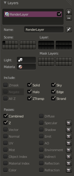

Editor's note
You need to find how to associate one camera with one render layer
::编辑的注意 你需要找到如何将一个摄像机与一个染层关联Then go the Node Editor and click on the button with a human face. Click on Uses nodes and remove the created items by selecting the items and clicking on Del . Now, using the Add menu, you need to do this diagram:
::然后进入节点编辑器,点击带有人脸的按.点击使用节点,并通过选择项目并点击Del删除创建的项目.现在,使用添加菜单,您需要做这个图表: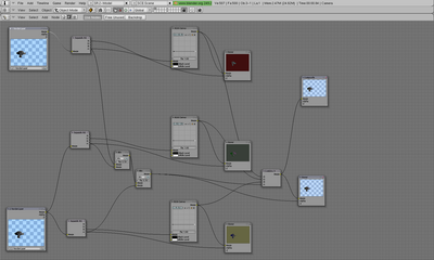
Once done, return to the Buttons window and select the button Do Composite on the Anim tab:
::在 Anim 选项卡上选择"做组合"按: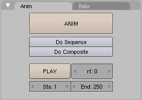
Then click on the button Render on the Render tab:
::然后点击"染"按在"染"选项卡上: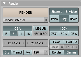
You should see your objects as an anaglyph:
::你应该把你的物体看作是个形文字: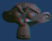
-
Reset the cameras position, rotation and size (you can use Alt + G , Alt + R and Alt + S ). You may want to note these values first, so you can change them back later. I just make sure there's an IPO-curve for them, for example by making a keyframe ( I ).
-
Spherical Blend Texture
::球形混合质地This technique maps a spherical blend texture to the outsides of an object.
::这种技术将球形混合质感映射到物体的外面.Create a new material and name it something intelligent. Create a new texture for this material, change the texture type to Blend, and then in the texture properties, change the blend shape to "Sphere".
::创建一个新的材料并给它命名为智能. 创建一个新的质地, 将质地类型更改为Blend, 然后在质地属性中, 将混合形状更改为"球体".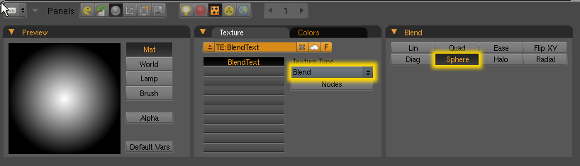
Back in the material buttons, go the "MapInput" tab and change the texture coordinates to Blank-Blank-Z and Nor and as demonstrated in the next screenshot: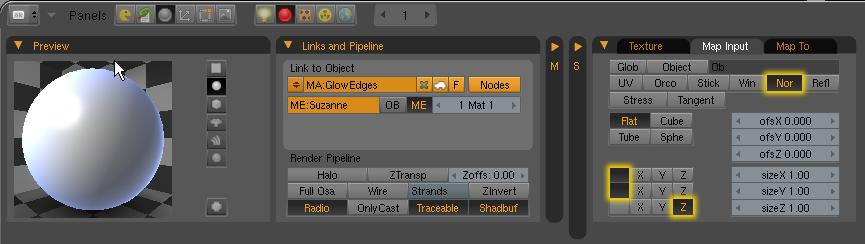
::在材料按中,请进入"MapInput"选项卡,并将纹理坐标更改为Blank-Blank-Z和Nor,如下面的截图所示:
Finally go the "MapTop" tab, and depress the Emit button and set the Texture Blending Mode to "Add":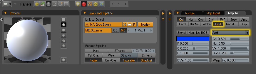
::按下发送按,并将纹理混合模式设置为"添加":That's all there is to it, and here is how it looks:
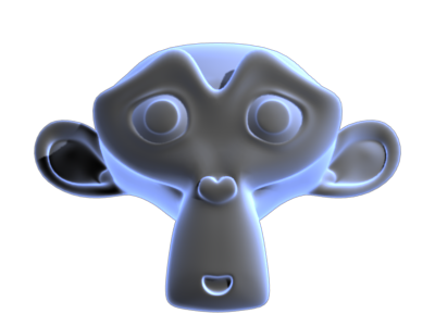
::这就是它所要做的,
Backlighting
::背光照明This is a technique that a rather famous blender user called "@ndy" uses. Very simple and effective.
::这是一个名为"@ndy"的混合器用户使用的技术.All you need to do is place a Hemi light BEHIND the object you want to light in respect to the active camera.
::您只需要在想要照射的物体后面放置一个 Hemi 灯,Breakdown: First add a Hemi lamp to your scene:
::细分:首先在你的场景中添加一个Hemi灯:

Next, Select the lamp THEN press and hold down the Shift key, and select the Camera. Press Control-C to bring up the copy attributes menu, and copy location AND rotation.
::接下来,选择灯然后按住Shift键,选择摄像头. 按C控键显示复制属性菜单,复制位置和旋转.

Now select JUST your lamp, press R to rotate it, then press the X key TWICE to rotate around the local X axis. Using your numpad, key in "180" to rotate the object 180Degrees.
::现在选择你的灯,按R旋转它,然后按X键两次旋转在当地的X轴. 使用你的板,键在"180"旋转对象180度.All that remains to do is to press G to grab the lamp, then press Z TWICE to move along the local Z axis, and move the lamp until it is past and behind the object of interest. your resulting setup should look something like this:
::剩下的就是按G抓住灯,然后按Z两次沿着当地的Z轴移动,并移动灯直到它过去和后面的兴趣对象.

And here is the rendered result:
::这里是染结果:
-
Color ramp
with input set to normal.
::输入设置为正常.
Pretty straighforward, but many advise against it.
::虽然很直接, 但很多人建议不要这样做.-
Minnaert shader
::的影子
Available in 2.37, "Darkness"<1 actually brightens edge. A cool shader, but not very useful for this purpose.
::提供2.37版本, "黑暗"<1实际上会亮出边缘. 一个很酷的遮光器,但不太适合这个目的.
-
Color ramp
with input set to normal.
-
This tutorial should cover the modelling, skinning and animation of human body, plus facial expressions.
::对于这些人来说,There are some tools to generate human body from parameters like:
::有一些工具可以从以下参数生成人体:-
makehuman
free software program (gpl). The models generated are under MIT license. The models generated can be easily imported in blender.
::制作人是免费软件 (gpl).生成的模型是MIT许可证下.生成的模型可以很容易地导入混合器.
Use lightwave(obj) export. The exported file is located at ...\Documents\makehuman
::使用光波输出. 导出的文件位于...\Documents\makehuman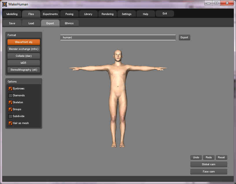
Delete the original cube first. The human object is smaller than the standard cube. Use the UVImage editor to see the UV mapping but it actually uses a texture stored in the image file texture.png
::首先删除原始立方体. 人物对象比标准立方体小. 使用UVImage编辑器查看UV映射,但它实际上使用存储在图像文件中的纹理.png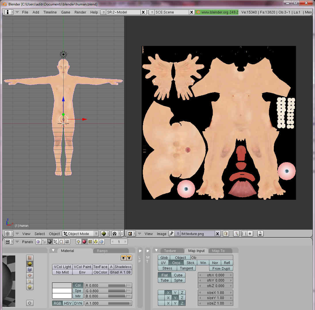
-
facegen
proprietary program. Used for
The Elder Scrolls IV: Oblivion
.
::面对专有程序. 用于"长老卷轴四:忘记".
links to anatomy sites :
::链接到解剖学网站:-
fineart
::艺术 -
Body proportions
::机身比例
tutorials: Blender 3D: Tutorial Links List
::教程: 混合器 3D: 教程链接列表
-
makehuman
free software program (gpl). The models generated are under MIT license. The models generated can be easily imported in blender.
-
You can append libraries in two ways. You can make a local copy of data blocks (like objects, meshes, ...) of the content of a .blend file in your .blend file ( appending ) or you can use data blocks from another .blend file ( dynamic linking ).
::您可以通过两种方式添加库.您可以在您的 .blend 文件中对数据块 (如对象,网格等) 的内容进行本地复制 (添加) 或您可以使用来自另一个 .blend 文件的数据块 (动态链接).You can Append with the command in the 3d view File -> Append or SHIFT+F1 . When you give this command a file browser window opens. There are two buttons Append and Link at the bottom of the window. The default action is appending . But you can use dynamic linking selecting the link button.
::您可以使用3D视图文件 -> 添加或SHIFT+F1中的命令添加. 当您执行此命令时,文件浏览器窗口会打开. 窗口底部有两个按添加和链接. 默认操作是添加. 但是您可以使用选择链接按的动态链接.At this point select the .blend file to append. You can select one of the following data blocks type to append:
::在此时点选择要添加的.blend文件.您可以选择以下数据块类型中的一个来添加:-
Group
::组 -
Mesh
::网格 -
Object
::目的 -
Scene
::场景 -
Text
::文字 -
World
::世界
Note that this is a complete list, when you append only block types present in the file will appear. Select the desired type. Now you can select the particular data block to append by selecting its id.
::请注意,这是一个完整的列表,当你添加时,只会显示文件中存在的块类型. 选择所需类型. 现在你可以通过选择其 id 来选择添加的特定数据块.Indirect linking
::间接链接When you give an append or link command almost all relations between data blocks in Blender get expanded. For example, when you link (or append) a specific Group, all its objects, the meshes associated with the objects, the materials and the animations will be linked (or appended) too. That is called "indirect linking". When you use dynamic linking such indirect linked data is not stored when you save a .blend file, when you load the file again blender will look for the indirect linked data blocks in the library file.
::当你给一个附加或链接命令时,Blender 中数据块之间的几乎所有关系都会得到扩展.例如,当你链接 (或附加) 一个特定的组时,其所有对象,与对象相关的网格,材料和动画也会被链接 (或附加).这被称为"间接链接".当你使用动态链接时,当你保存一个 .blend 文件时,这种间接链接的数据不会被存储,当你重新加载文件时,Blender 将在库文件中搜索间接链接的数据块.Groups
::组When you append a Group, blender will also create links in the current Scene to the objects that are part of the group. The Objects then become visible. However, when you decide to dynamic link a Group, it won't do that. To use the objects in your blender project you can use the group as a duplicator " SHIFT+AKEY -> Group menu -> group id to duplicate".
::当你添加一个组时,混动器也会在当前的场景中创建链接到组中的对象.然后对象会变得可见.但是,当你决定动态链接一个组时,它不会这样做.要在你的混动器项目中使用对象,你可以使用组作为复制器"SHIFT+AKEY -> 组菜单 -> 组ID复制".
-
Group
-
Now that you've gotten the hang of 3D modeling, it's important to get some community feedback on your progress. Don't be an idiot and skip this part, or you'll regret it later. Basically this will help you track your progress and give you something that you'll be working on over a long term and something you'll be proud of.
::现在你已经掌握了3D建模, 重要的是要得到社区对你的进展的反. 不要做个瓜, 跳过这个部分, 否则你会后悔. 基本上, 这将帮助你跟踪你的进展, 并给你一些你将在长期工作的东西, 你会为之感到自豪.-
First, you need to come up with a project idea. You can choose your own modeling project, or choose one from the list below.
::首先,你需要想出一个项目.你可以选择你自己的建模项目,或从下面的列表中选择一个.
-
Second, you need to create a model of your idea. Spend a couple of hours on it, and give it some details.
::首先,你需要创建一个模型,
-
Third, once you believe you've come far enough with the model, post it in the
Works In Progress
forum on BlenderArtists.org(formerly elysiun.com) (you will have to create an account if you haven't already). Post several screenshots of your model from within the Blender (note: creating screenshots is outside the scope of this wikibook, though see note lower down the page). You can post whatever subject and message with your posting that you would like, or you can use this suggested subject and message:
::第三,一旦你认为你已经足够深入地完成了模型,就在BlenderArtists.org (以前的elysiun.com) 的Works In Progress论坛上发布它 (如果你还没有创建一个帐户,你必须创建一个帐户).从Blender中发布你的模型的几个截图 (注意:创建截图是本维基本的范围之外的,但请参阅页面下方的注释).你可以随着你的帖子发布任何你想要的主题和信息,或者你可以使用这个建议的主题和信息:
- Subject: Beginning Modeling Final Project - <project name>
-
- Please assist me with any feedback on my model, keeping in mind that I am an absolute beginner still. I appreciate your help.
-
Wait for feedback. It usually comes very quickly. If you have any questions about feedback that you are given, don't be afraid to ask your questions in the forum.
::期待反.通常会很快.如果你对你得到的反有任何疑问,请不要害怕在论坛上提出问题.
-
When you and others that have viewed your work feel that you are ready, save your model in some place you can get back to easily. You will continue working on this project once you've learned some new skills.
::您可以将模型保存到您可以轻松返回的地方. 一旦您学会了一些新技能,您将继续在这个项目上工作.
-
Move on to the next page.
::转到下一页.
(BTW. in Windows and/or maybe other OS, to take a screenshot press 'PrtScn' (PrintScreen). It will copy the screen to clipboard for you to paste in your favourite graphics application. This may not work in other OSs but try anyway. You can also create Blender screenshot directly from Blender using menu File>Dump 3DView... or File>Dump Screen... )
:(In linux under the KDE I use ksnapshot, check under the graphics tab and see if you have it. If not it should be just a google search away
gl and happy blendering)
::查看图形标签下是否有. 如果没有, 应该只需在谷歌搜索(On Mac OS X, press Command (Apple) + Shift + 3 to do a full screen capture)
:-
List of ideas:
::想法列表: -
A Computer and keyboard
::计算机和键盘 -
A fishing rod
::一根鱼棒 -
A train engine
::一个火车发动机 -
A skyscraper
::一座摩天大楼 -
A robot
::一个机器人 -
A Tank (real or made up)
::一个坦克 (真实或虚构) -
An airplane
::一架飞机 -
A truck or car
::一辆卡车或汽车 -
Household appliances
::家庭用电器 -
A Weapon
::一种武器
-
First, you need to come up with a project idea. You can choose your own modeling project, or choose one from the list below.
-
Introduction to Inkscape
::介绍InkscapeInkscape is a free program that uses SVG (Scalable Vector Graphics) for its file format, and these SVG files can be imported into blender as Bezier curves. Inkscape has some great tools for making advanced shapes that would take forever to make in Blender itself. We will use Inkscape because it is free, and it is very easy to learn.
::印斯凯普是一个免费的程序,它使用SVG (可扩展矢量图形) 作为文件格式,这些SVG文件可以作为贝齐尔曲线导入混合器.印斯凯普有一些很好的工具来制作高级形状,而在混合器本身需要一子.我们将使用印斯凯普,因为它是免费的,并且很容易学习.Installing Inkscape
::如何安装Inkscape-
Mac OS X and Windows
: Go to
Inkscape.org
and click download. there will be installation files for each operating system.
::进入Inkscape.org并点击下载. 每个操作系统都会有安装文件. -
Linux
: Go into the terminal.
::进入终端.
For Arch Linux, type pacman -S inkscape
For Debian based distributions, type sudo apt-get install inkscape
For Fedora and rpm based distributions, type yum -y install inkscape
For any other distribution, check your package manager to see if it has a package for inkscape. if not, download the source code at Inkscape.org and run PKGBUILD in the directory of the source.
::对于Arch Linux,输入 pacman -S inkscape对于基于Debian的发行版,输入 sudo apt-get install inkscape对于基于Fedora和rpm的发行版,输入 yum -y install inkscape对于任何其他发行版,请检查您的包管理器是否有 inkscape 的包. 如果没有,请从Inkscape.org下载源代码,并在源目录中运行PKGBUILD.Inkscape is a pretty large program, so it will take a while to download and install.
::这是一个相当大的程序,所以下载和安装需要一段时间.Getting Started
::开始Because blender doesn't import any effects or filters from SVG files, we will only have to learn basic path modeling. This is very easy to learn, and will take no time at all. Once it's finished installing, open Inkscape. You will see a large empty page and a bunch of buttons to the left. Don't mind the empty page, we won't be needing it. We will re-size this once we are done with the tutorial. Before we get started, I will show you how to use some of the controls. You will probably be right clicking a lot because you're used to blender, but that's okay. Let's start out with a star to practice some of the controls. Click the Star/Polygon tool to the left, and click anywhere on the paper and drag.
::由于混合器不从SVG文件中导入任何效果或过器,我们只需要学习基本的路径建模.这很容易学习,而且不会花费时间.一旦安装完成,打开Inkscape.您将看到一个大空页面和左边的一堆按.不要介意空页面,我们不需要它.我们将在完成教程后重新调整尺寸.在我们开始之前,我将向您展示如何使用一些控制.您可能会经常点击右键,因为您已经习惯了混合器,但没关系.让我们从一颗星开始练习一些控制.点击左边的星/多边形工具,然后点击纸上的任何地方并拖动.Simple Controls
::简单的控制go back to "Object Mode" by clicking the cursor icon to the left. Now, let's try out some of the controls:
::现在,让我们尝试一些控制:Action Hotkey Zoom In/Out CTRL+SCROLL Move along Y Axis SCROLL Move along X Axis SHIFT+SCROLL Move along both axes Hold MMB and Drag Select Path/Curve LMB Select All CTRL+A Select all paths/curves within a rectangle Hold LMB and drag (Like selecting icons on your desktop) These are only a few of the controls, you will learn more controls later in this tutorial.
::您将在本教程中学习更多的控制.Editing your Bezier path
::编辑您的贝齐尔路径Go back to the Star/Polygon tool so we can edit the star. You will see 2 dots appear on the star. You can drag these around, and see what happens. Another thing you can do is add more points to the star, change the spike ratio, make it rounded, and make it randomized with the "CHANGE:" Dialog right above your image.

::现在我们可以使用"星/多边形"工具来编辑星. 星上会出现两个点. 你可以拖动它们,看看会发生什么. 还有一件事是,你可以在星上添加更多点,改变尖峰比率,使其圆形,并通过"CHANGE:"对话框在图像上方随机进行.If you want to edit each node separately without symmetry, go back to 'Select and Transform Objects' mode
 and click Path>Object to Path. Now you can just go to 'Edit Paths by Nodes' mode
 and play around with the shape a bit.
::如果您想单独编辑每个节点而没有对称性,请回到'选择和转换对象'模式,然后单击路径>对象到路径. 现在您可以进入'编辑节点路径'模式,并稍微玩弄形状.By clicking and dragging, you can move a node or curve an edge. when you make a curve, 2 nodes will show up that you can drag and edit the curve with more precision.
::通过点击和拖动,你可以移动一个节点或曲边缘. 当你做一个曲线, 2节点会显示出你可以拖动和编辑曲线更精确.To add a node in the path, select an edge and press the plus button
 to remove a node, press the minus button, and, well, the buttons pretty much explain themselves, so you can just play around and see what you get.
::按下加号按去除一个节点,按下减号按, 按几乎可以自己解释,After you think you know how to edit paths pretty well, let's try to make a path from scratch. Click the 'Draw Bezier Curves' button
 and click to add nodes for the shape you want. If you click and drag, you will make a node and curve the node while dragging the mouse. To finish the path, go around to the first node that you made and click on it. This will finish the path and make it a solid shape. When it is done, a outline, or stroke of the shape will appear. If you want it to show as a solid shape, you can click one of the colors on the bottom and it will fill the path with that color.
::现在,我们可以尝试从头开始创建路径. 点击'画贝齐尔曲线'按,然后点击添加你想要的形状的节点.如果点击和拖动,你会在拖动鼠标时创建一个节点并曲线节点. 完成路径,转到你创建的第一个节点并点击它. 这将完成路径并使其成为一个固体形状. 当它完成时,将出现一个轮或图形的图形. 如果你希望它显示为一个固体形状,你可以点击底部的颜色之一,它将以该颜色填充路径.Now, move the star inside the path (In 'Select and Transform Objects' mode, of course), without it overlapping the borders of the path. If the star is too big, scale it down and hold ctrl to keep the same scale on the X and Y axis. Select both your path and the star, and press Path>Difference to cut a star-shaped hole inside your path.
::现在,将星移到路径内 (当然在'选择和转换对象'模式下),不要让它重叠路径边界.如果星太大,缩小它,并按住ctrl以保持X和Y轴上的相同尺度.选择你的路径和星,然后按路径>差异,在你的路径内切割一个星形孔.Congratulations, You have made a completely pointless random shape and learned the basics of creating a shape in inkscape! Now, It's time to get this into Blender! Save your SVG image, and open up blender. Press File>Import>Paths(.svg, .ps, .eps, .ai, gimp) (Blender 2.49). Select your SVG file and the settings are fine how they are. Press OK and see your path appear in blender (You may have to delete the default cube to see it) From here, you can Extrude, bevel, and do whatever you want to you bezier path in blender.
::恭喜你,你已经做了一个完全无用的随机形状,并且学会了在Inkscape中创建形状的基础!现在,是时候把这个带到Blender了!保存你的SVG图像,然后打开Blender.按文件>导入>路径 ().svg, .ps, .eps, .ai, gimp) (Blender 2.49).选择你的SVG文件,设置是好的.按OK,然后在Blender中看到你的路径 (你可能需要删除默认的立方体才能看到它) 从这里,你可以挤出,曲,以及你想要在Blender中做任何你想要的路径.The result may look something like this:

::结果可能看起来像这样:
-
Mac OS X and Windows
: Go to
Inkscape.org
and click download. there will be installation files for each operating system.
-
The Platonic solids or Platonic polyhedra are the convex polyhedra where all faces are copies of the same regular polygon, and the same number of edges meet at every vertex. There are five of these shapes: the tetrahedron (like a pyramid but with a triangular base): cube, octahedron, dodecahedron and icosahedron.
::柏拉图的固体或柏拉图的多面体是凸的多面体,其中所有面都是同一正规多边形的复制品,并且每个顶点的边数相同.这些形状有五种:四面体 (像金字塔,但有三角形底座):立方体,八面体,十二面体和二面体.Recent versions of Blender include an addon called “Regular Solids”, which lets you instantly generate these and a whole bunch of other similar shapes. However, the following steps do not require any addons.
::最近的Blender版本包括一个叫做"常规固体"的附加功能,它可以让你立即生成这些和其他类似的形状.然而,以下步骤不需要任何附加功能.The Tetrahedron
::四面体Bring up the Add Mesh menu (Shift+A), and select a Cone. Set the number of Vertices to 3, leave Radius 1 at its default value of 1.000 and Radius 2 at 0.000 [1] . Now, set the Depth to . To make sure that you have a regular tetrahedron, you can check the lengths of the edges (in Edit Mode, press N to open the Properties panel and locate the checkbox Length in the section Edge Info ).
::打开"添加网格"菜单 (Shift+A),选择一个圆.将顶点数设置为3,将半径1设置为1.000和半径2设置为0.000[1].现在,将深度设置为2 ≈ 1.414 .为了确保您有一个正规的四面体,您可以检查边缘的长度 (在编辑模式中,按N打开属性面板,并在边缘信息部分找到选项框长度).The Cube
::立方体This happens to be a built-in shape in Blender. Just bring up the Add Mesh menu, and select Cube. Done!
::现在,我们可以使用Blender来选择一个模块.The Octahedron
::八面体This shape is the dual of the cube—it has vertices where the cube has faces, and faces where the cube has vertices. To make it, first create a cube. Press Tab to switch to Edit mode. All the vertices should already be selected. Press W to bring up the Specials menu, and select the Bevel function (or select it directly with CTRL + B ). As you move the mouse, you will see each vertex of the cube turn into a triangular face; don’t bother getting the shape exactly right, simply press LMB to finish the drag. Then, look in the panel that should have appeared at the bottom of the Toolshelf on the left of the 3D view (press T to toggle its visibility); you should see an editable numeric field labelled “Offset”. Type the value 1.0 into this field, and that should exactly form the octahedron shape.
::这种形状是立方体的双面,它有立方体有面的顶点,有立方体有顶点的面. 要制作它,首先创建一个立方体. 按 Tab 切换到编辑模式. 所有的顶点应该已经被选中. 按 W 显示 Specials 菜单,并选择 Bevel 函数 (或直接使用 CTRL + B 选择). 当您移动鼠标时,您会看到立方体的每个顶点变成三角形面; 不要费心准确地定制形状,只需按 LMB 完成拖动. 然后,在 3D 视图左侧的工具架底部显示的面板中查看 (按 T 切换可见性);您应该看到一个可编辑的数字字段标记为 偏移. 将值输入此字Finally, bring up the Specials menu again, and this time select Remove Doubles [2] .
::最后,再次打开"特殊菜单",这次选择"删除双重物品"[2].The Icosahedron
::图形象面Bring up the Add Mesh menu, and select an Icosphere. Set the Subdivision to 1. Simple!
::打开"添加网格"菜单,选择一个Icosphere. 设置分区为1. 简单!The Dodecahedron
::十二面体This shape is the dual of the icosahedron. To create it, make an icosahedron as above. Then do what you did to make an octahedron out of a cube: press Tab to switch to Edit mode. All the vertices should already be selected. Press W to bring up the Specials menu, and select the Bevel function. As with the octahedron, press LMB to finish the drag. Then set the Offset value to 0.30310889132, which comes from the formula , with being the edge length of the icosahedron (1.05 if made by the method above) [3] .
::这种形状是二元的. 为了创建它,做一个二元如上所述. 然后做你做了一个八面体从一个立方体:按键 Tab 切换到编辑模式. 所有的顶点应该已经被选中. 按W 带来特殊菜单,并选择曲函数. 与八面体一样,按 LMB 完成拖动. 然后设置的偏移值为0.30310889132,这是来自公式a 3 6 ,与一个是边缘的二元长 (1.05如果通过上述方法).Then, bring up the Specials menu again, and this time select Remove Doubles [4] , you should see the message “Removed 40 vertices” briefly flash up.
::然后,再次打开"特殊"菜单,这次选择"删除双重点",[4]你应该看到"删除40个顶点"短暂闪现.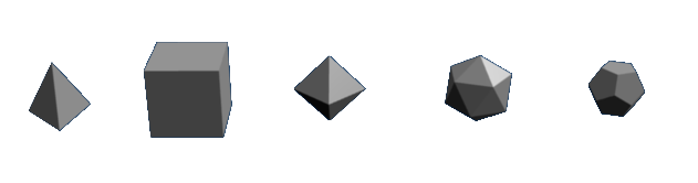
Exercise
::运动What’s the dual of the tetrahedron? Try applying the Bevel operation to one of those; what do you end up with?
::试试把贝维尔运算应用到其中一个,最终得到什么?
-
Blender 3D: Animation Notes and FAQ
::Blender 3D:动画笔记和常见问题IMPORTANT
::重要的是This page is under heavy construction. It will probably not be edited better until early May 2012. If someone sends me information on how to convert a OpenOffice odt file to a wikidoc format, then it may be done sooner. Until then this will be quite a work in progress.
::这页正在重建中.它可能不会在2012年5月初才更好地编辑.如果有人向我发送有关如何将OpenOffice odt文件转换为wikidoc格式的信息,那么它可能会更快完成.直到那时,这将是一个正在进行中的工作.Authors & Contributors
::作者和贡献者See here .
::看看这里.Introduction
::引言 时间I found it quite cumbersome to find all of the little quirks, problems, and tricks in multiple sources whenever I would forget something. Therefore, I compiled all of the things I found important—primarily with character animation. Almost all the information here is consolidated from many sources. Some sources still need to be cited and any help on this would be much appreciated. For that reason I did not intend to make this public but I think there is enough need for this type of information so here it is.
::我发现在多个来源中找到所有小怪癖,问题和技巧是相当繁的.因此,我编译了我认为重要的所有东西,主要是与角色动画有关.几乎所有信息都来自许多来源.还需要引用一些来源,任何帮助都会非常感激.因此,我不打算公开这个信息,但我认为有足够的需要这种类型的信息,所以这里是.Just as a special aside, I made these notes to help myself with my animation project. Although I have organized them and posted them online for my and others benefit, I will not be dedicating any large amount of time to this website. All of my extra time needs to be allocated to the animation project. However, I do not mind suggestions and am willing to possible use them. I want to make sure that the viewer understands my time is very limited.
::作为一个特殊的旁边,我做了这些笔记,以帮助自己与我的动画项目.虽然我已经组织和在线发布他们为我和其他人的利益,我不会奉献任何大量的时间,这个网站.我所有的额外的时间需要分配给动画项目.然而,我不介意建议,并愿意可能使用它们.我想确保观众理解我的时间是非常有限的.There may be many typos or confusing areas of organization. I tried to organize the mess of notes as best as possible but I am sure there is an even better way. Feel free to fix any aspect of this.
::我试图尽可能地整理这些混乱的笔记,但我相信还有更好的方法. 请随时纠正任何方面.Any suggestions or comments feel free to e-mail me at wiki [at] pagodaproductions.com.
::任何建议或评论可以随时发送给我,Todo List
::工作列表See here .
::看看这里.Animation FAQ
::动画常见问题Armatures
::骨架Q: I managed to create an acceptable walk cycle finally, now when I reopend the file to add additional animation, It keeps falling back to walk cycle, is their something i am doing wrong. Even after adding the LocRotScale key frame, it still ignores them, and goes back the corisponding frame for the walk. Ugggghhhh!!!
::问:我终于设法创建了一个可接受的步行周期,现在当我重新打开文件以添加额外的动画时,它一直会回到步行周期,这是我做错的事情.即使添加了LocRotScale键框,它仍然会忽略它们,并返回步行的相应.Q: What is the best approach for rigging a character in Blender?
::问:在Blender中操纵一个角色的最佳方法是什么?Q: How do I attach a separate object to a bone?
::问:我如何将一个单独的物体连接到骨头上?Q: When you try to scale the root bone of the armature(which scales the mesh), the bones move out of the natural placement causing unwanted positioning and distortion. Is there any way around this?
::问:当你试图缩放具的根骨 (这缩放了网状物) 时,骨头会移出自然位置,导致不必要的定位和扭曲.有没有办法绕过这个问题?Q: What is a pole vector?
::问:什么是极向量?Q: How do I know that my armature is correctly positioned in global space in edit, object, and pose mode with proper bone rolls and axis pointing in proper directions? What are the best methods for building? And what axis is up Y or Z?
::问:我如何知道我的具在编辑,对象和姿势模式下正确地在全球空间中定位,有适当的骨滚和轴向正确的方向? 构建的最佳方法是什么? 什么轴是Y或Z?Hotkeys
::热键Ctrl-C/Ctrl-V Trick One simple way to get the right name is to select the Lattice, go to F9, Link and Materials panel and where it says Ob:Lattice or Ob:Lattice.001 etc., move the mouse over this field and press Ctrl-C (don't click on it, just hover over it). This copies the Lattice name. Then select your object, go to the Lattice Modifier panel, hover the mouse over the Ob: field and press Ctrl-V to paste the name in. Now it should stay there and your Lattice should work in Edit Mode.
::Ctrl-C/Ctrl-V 技巧 获取正确名称的一个简单方法是选择格子,进入F9,链接和材料面板,在上面写着Ob:Grid或Ob:Grid.001等,将鼠标移动到这个字段上,然后按Ctrl-C (不要点击它,只需在上面移动). 这复制了格子名称. 然后选择你的对象,进入格子修改器面板,移动鼠标移动到Ob:字段上,然后按Ctrl-V粘贴名称. 现在它应该留在那里,你的格子应该在编辑模式中工作.H hides bones
::皮的骨头Alt+H shows all bones
::Alt+H显示所有骨头Shift+H hides everything except the chain
::转换+H 隐藏除了链的所有东西Ctrl+I [Pose Mode] will automatically add an IK contraint
::Ctrl+I [立场模式] 将自动添加一个 IK 约束M [Pose Mode] to move a bone to a bone-layer, select it in POSE mode then press "m" and click on the desired layer button. When the bone is selected, you can see which bone layer it is on in the Editing buttons / Selected Bones panel. Whichever of the 16 layer buttons is enabled is the layer the bone will be on.
::M [Pose Mode] 移动骨头到骨层,选择它在POSE模式,然后按"m"并点击所需的层按.当骨头被选择时,您可以在编辑按/选择的骨头面板中看到它在哪个骨层. 启用16个层按中的任何一个都是骨头将在哪个层.Shift+M [Pose Mode] You can use the hotkey SH-M to display a floating bone-layer panel in the 3d viewport. Select the armature, change to POSE mode, then change to the Buttons/Editing panel (F9). Under the Armature-Panel, Display Options SH-LMB the 8th button under the Display Options Bone-Layer buttons to enable it. Check out this by BlenderArtists.com.
::转换+M [姿势模式] 您可以使用快键SH-M在3D视窗中显示浮动骨层面板. 选择具,切换到POSE模式,然后切换到按/编辑面板 (F9). 在具面板下,显示选项SH-LMB在显示选项骨层按下的第8个按以启用它. 查看此由BlenderArtists.com.Alt-N normalize the bone orientation This can fix problems sometimes.
::这有时可以解决问题.Alt+P clears parent
::关闭父组合Alt+S [Pose Mode] in edit mode allows b-bones shape to scale visual changes without affecting the bones.
::在编辑模式中,Alt+S (姿势模式) 允许b-bone的形状在不影响骨头的情况下进行视觉变化.W [Edit Mode] subdivides bones
::W [编辑模式] 分别骨W [Pose Mode] will calculate paths to see how a bones movement is mapped out along a path or If you've named your bones correctly ( with .L and .R at the end of the name ) , you can flip the mirrored bone name by pressing "W" and "flip name" . A relevant post on BlenderArtsists.com is available here .
::按"W"和"翻转名字"就可以翻转骨头的名称.BlenderArtsists.com的相关文章可以在这里找到.Approaches, Techniques, Tips and Tricks
::方法,技术,技巧和技巧Constraining IK or FK In the Armature Bones Panel is where you can limit the movement of the bone for IK and Limit Rotation Constraint for FK
::在具骨面板是你可以限制骨的运动,以 IK 和限制旋转限制FKCustomizing Frame Skipping Steps(F10 playback) allows for a customizable way of skipping frame in increments.
::定制跳转步骤 (F10播放) 允许在增加的跳转的可定制方式.
Copying Constraints in pose mode 1. Select all bone(s) you wish to copy the constraints to, from a particular bone 2. Now, select the bone you wish to copy constraints from 3. Ctrl C --> Constraints (All)
::在姿势模式下复制限制 1. 选择所有骨 () 您希望复制限制,从特定的骨 2. 现在,选择您希望复制限制的骨 3. Ctrl C --> 限制 (全部)You can do CTRL-CKEY to copy stuff from a bone to bones. The options are location, rotation, scale and constraint. Constraint is very handy when you wan to copy a constraint to other bone. The way it works is easy. The WKEY menu get some neat options too: Select constraint target: Will select the target of the bone's constraint currently selected. Flip name: Yep, you can flip name in Posemode too. Calculate/Clear path: This is a visual way to see the action linked to your armature. You can select just some bones and ask Blender to show you the paths of the bones.
::您可以使用CTRL-CKEY从骨头复制到骨头. 选项是位置,旋转,尺度和约束. 当您想要将约束复制到其他骨头时,约束非常方便. 它的工作方式很简单. WKEY菜单也提供了一些简单的选项: 选择约束目标: 将选择当前选择的骨头约束的目标. 翻转名称: 是的,您也可以在Posemode中翻转名称. 计算/清除路径: 这是一个与具相关的动作视觉方式. 您可以选择一些骨头并要求Blender显示骨头的路径.It's possible to copy constraints from one object/bone to a bunch of objects/bones. A useful thing to know when doing a repetitive task like rigging all the fingers of a hand. Just select all bones/objects that you want to give a copy of the constraint, and then select the bone/object containing the constraints. Press CTRL-CKEY in 3DView, and select Object Constraints from the popup menu. The idea behind this is to copy the constraints of the active object to the selection.
::复制一个对象/骨的约束是可能的.当做重复任务时,如对手指进行改时,这是一件有用的事情.只需选择所有想要复制约束的骨/对象,然后选择包含约束的骨/对象.在3DView中按Ctrl-CKEY,然后从弹出菜单中选择对象约束.这背后的想法是将活动对象的约束复制到选择中.
Rigging Q: What is the best approach for rigging a character in Blender?
::操纵问:在Blender中操纵一个角色的最佳方法是什么?A: Apollux Honestly, I don't think that there is a golden set-up that will solve all your problems. For example, when I design a character rig I need to know beforehand what type of actions he will perform.
::答:阿波罗克斯 坦白说,我不认为有什么金色的设置可以解决你的所有问题.例如,当我设计一个角色的装备时,我需要事先知道他将执行什么类型的行动.If you want general pointers, I guess this would do: Allways set your rigs in a half relaxed fashion.. totally relax your hand for a few minutes and see the position of the palm and fingers, that is position you should model and rig-them on the 3D world. Same goes for mouth, legs, arms, etc. etc. etc.
::如果您想要一般指针,我想这会做:总是设置你的钻机在半放松的方式...完全放松你的手几分钟,看看掌和手指的位置,这是位置你应该模型和-他们在3D世界.When in doubt over IK or FK always choose IK, since it is quite easy to switch a IK rig into FK when needed and then back to IK.
::对于 IK 或 FK 选择,请始终选择 IK,因为在需要时,很容易将 IK 钻机切换为 FK,然后再重新切换为 IK.Bone's axis orientation can't be an afterthought!! It is no coincidence that every self-respecting rigging tutorial for blender mention it... And don't trust blindly on the automatic axis orientation fix command (Ctrl-N), since it can introduce some odd solutions on complex armatures. Always check each bone by hand, even if Blender says they are fixed.
::骨的轴方向不能是事后的!! 没有偶然的,每一个自尊的调试教程都提到它... 不要盲目地相信自动轴方向修复命令 (Ctrl-N),因为它可以在复杂的具上引入一些奇怪的解决方案. 总是手动检查每个骨头,即使Blender说它们是固定的.Ultimate rig design is not the in-and-all of character animation. Sometimes I would spent crazy amounts of time preparing a rig for a special squence, and in the end realize that if I had used a simple FK rig tricked by hand during animation I would get the same results in half of the time and half the frustration. Not because it can be done means that it must be done. BlenderArtists post here .
::终极轮设计不是角色动画的全部. 有时我会花费大量的时间来为特殊的动画编制轮,最后意识到如果我在动画中使用一个简单的手工的FK轮,我会在一半的时间和一半的挫折中得到相同的结果. 不是因为它可以做到,这意味着它必须做到. 混合器艺术家在这里发布.
Item Pickup A good use of it is to ask a character to pick up something. By having a bone or empty for each side of the relationship (hand <-> glass), as the hand approaches the glass, you can align the two empties and fire the constraint up (1.00) to stick them together. You add another child-bone in the middle of the hand to tell where the glass will be. Thus moving the hand will move the glass. On the side of the glass just add an empty and make it parent of the glass. Add a copy location to the empty pointing to the bone in the hand we just did. There you go. Of course when the hand rotates the glass will not. For that you will need to add a Copy Rotation Constraint. Before Blender 2.40, the above method was a good way of faking parent relationship without rotation. But now we have the hinge option which does the same.
::取物件 很好的使用方法是让一个角色取东西.通过在关系的每一边 (手 <-> 玻璃) 设置一个骨头或空洞,当手接近玻璃时,你可以对齐两个空洞,并将约束 (1.00) 激活,将它们粘在一起.你在手的中间添加另一个子骨头来告诉玻璃将在哪里.这样移动手将移动玻璃.在玻璃的一边只需添加一个空洞,使其成为玻璃的父.在空洞的位置上添加一个复制位置,指向我们刚才做的手中的骨头.你就在那里.当然,当手旋转时,玻璃不会.为此,你需要添加一个复制旋转约束.在Blender 2.40之前,上述方法是假装父关系而不旋转的Problems and Questions
::问题和问题Separate Object/Bone Attachment Q: How do I attach a separate object to a bone?
::单独的物体/骨附着 Q:我如何将单独的物体附着到骨上?A: To do that simply Ctrl-Tab into Pose Mode with the armature selected then select the object/mesh you want to parent to a bone then shift-select the bone you want to be the parent and Ctrl-P>"MakeParent to">Bone .
::答: 为了做到这一点,只需在选择了具时,单击Ctrl-Tab进入"姿态",然后选择您想要对骨进行父对象/网格,然后移动选择您想要为父对象的骨,然后单击Ctrl-P>"MakeParent to">Bone.
Armature Scaling Problems Q: I have been trying to scale my character which has many similarities to the mancandy and ludwig rigs. However, when you try to scale the root bone of the armature(which scales the mesh), the bones move out of the natural placement causing unwanted positioning and distortion. Both the mancandy and ludwig rigs have this same problem. Is there any way around this?
::装甲尺度问题:我一直在尝试将我的角色尺度化,它与曼坎迪和卢德维格钻机有很多相似之处.然而,当你试图将装甲的根骨 (这尺度是网状的) 进行尺度化时,骨头会移出自然位置,导致不必要的定位和扭曲.曼坎迪和卢德维格钻机都有同样的问题.有没有办法解决这个问题?A: Why are you trying to scale the root bone (to scale the whole model)? Are you doing this in pose mode or object mode? If you are trying to scale the whole model try it in Object Mode. Also check if you are scaling around the cursor instead of median point
::答:为什么你试图缩放根骨 (缩放整个模型)?你是在姿势模式或对象模式中做吗?如果你试图缩放整个模型,请尝试在对象模式中.还要检查你是否在光标周围缩放而不是中间点
Q: What is a pole vector?
::问:什么是极向量?A: Vertex Pusher 2) Pole vector is actually a term used in Maya. It refers to the direction a bone is set to point towards in Maya rigging. For example, the direction you want the knees to point towards can be set using pole vectors. Apparently, Blender should be getting this feature soon . Right now you have to add target bones so that the knees will only bend one way (see Ryan Dale's BSoD tutorial), but with the option to use pole vectors you won't need to do this in the future .
::答: Vertex Pusher 2) 极向量实际上是玛雅语中使用的术语.它指的是玛雅具中骨头设置的方向.例如,您想要膝盖指向的方向可以使用极向量设置.显然,Blender应该很快得到这个功能.现在您必须添加目标骨头,以便膝盖只能向一个方向曲 (参见Ryan Dale的BSoD教程),但随着使用极向量的选项,您将来不需要这样做.BlenderArtists post about bones .
::艺术家们发表关于骨的文章.Bone Orientation Q: How do I know that my armature is correctly positioned in global space in edit, object, and pose mode with proper bone rolls and axis pointing in proper directions? What are the best methods for building? And what axis is up Y or Z?
::骨定向 问:我如何知道我的具在编辑,对象和姿势模式中正确地定位在全球空间中,有适当的骨卷和轴向正确的方向? 构建的最佳方法是什么? 什么轴是Y或Z?A: 1. Build up all the bones, as you did before. (Every foot, arm, etc. should be a bit bent, and drawn from the proper view.)
::答: 1. 像以前一样, 建立所有的骨头. (每一个脚,手臂等都应该稍微曲, 并从正确的视角画出来.2. Select all these armatures, and with Ctrl-J join them into one armature. (Or with parent/child connection, as is necessary.)
::2. 选择所有这些具,并使用Ctrl-J将它们连接成一个具. (或根据需要使用父/子连接).3. Select this armature, go to "Editing" (F9), and then turn on "draw axes". Then you can see the axes of the bones. You will see, that the axes are different. Some bones has the Z-axis up, some has the Z-axis to the left, etc.
::3. 选择这个具,进入"编辑" (F9),然后打开"绘制轴".然后你可以看到骨头的轴.你会看到,轴是不同的.有些骨头的Z轴向上,有些骨头的Z轴向左,等等.4. First you should tell Blender that this is the original position of your skeleton/model by pushing Ctrl-A. This is applying rotation. This means, that now all the rotations of the bones will be "0, 0, 0", so if you push later Alt-R (clear rotation), you will get this position. (Turn on numerical menu with N, to see what happens when you make this apply rotation command.)
::4. 首先,你应该告诉Blender,这是你的骨架/模型的原始位置,按Ctrl-A. 这是在应用旋转. 这意味着,现在所有的骨头旋转将是"0,0,0",所以如果你稍后按Alt-R (清除旋转),你将得到这个位置. (打开数字菜单与N,看看当你使这个应用旋转命令时会发生什么.)5. Select the whole skeleton/model again. Go to edit mode. Then push A, to select all the bones. (They should be yellow now.) Then hit Ctrl-N, and you will see all the axises will be changed to stay on the same way.
::5. 再选择整个骨架/模型.进入编辑模式.然后按A,选择所有骨头. (现在它们应该是黄色的.) 然后按Ctrl-N,你会看到所有的轴会改变以保持相同的方式.6. That is, your skeleton now is ready to define the IK solvers, and then the skinning, and finally the animation.
::6. 现在你的骨架已经准备好定义了智能解决器,然后是剥皮,最后是动画.http://blenderartists.org/forum/showthread.php?t=25653
::通过一个新的平台,A: Vertex Pusher 4) Yes you should always add in top view[numpad 7]. An armature bone always has its axes set (Y is always up X side to side and Z depth) and you cannot change this like you can with mesh objects, so it seemingly won't matter which view you add a bone while in Edit Mode but in Object Mode your armature object will have a 90 degree rotation around the X axis (if you add it in front view) which can and usually does create problems down the road . If for some reason you want to add bones in front view simply start by adding the first armature bone in top view ad then switch to front view to add additional bones . You can just delete the first bone or rotate it while in Edit Mode .
::答: Vertex Pusher 4) 是的,你应该总是在顶部视图中添加. 具骨头总是设置了它的轴 (Y总是X侧向侧和Z深度),你不能像网状物体一样改变这个,所以在编辑模式下,你添加骨头的视图看起来并不重要,但在对象模式下,你的具物体将在X轴周围旋转90度 (如果你在前视图中添加它),这通常会造成问题. 如果出于某种原因,你想在前视图中添加骨头,那么简单地开始添加顶部视图中的第一个具骨头,然后切换到前视图中添加额外的骨头. 在编辑模式下,你可以删除第一个骨头或旋转它.Blender's default views have the Z as the "up" axis while the armature system is coded with the Y as the "up" (like most 3D apps)
::混合器的默认视图有Z作为"上"轴,而具系统是用Y作为"上" (像大多数3D应用程序)When you rotate a bone in the front view, when the bone is aligned to that view and the Z is the up axis, you will give a roll value the bone because it is rotating perpendicular to its coded up axis ... this can cause you problems in some situations when you want a "neutral" roll value in Pose Mode... in most cases you'll want to recalculate the roll value with Ctrl-N (which will remove the visible rotation and insert a value in the "Roll:" field in the Transform Properties subwindow) and give it a non zero roll value in Edit Mode so that in Pose Mode it is properly aligned and rotated for poses and constraints ...
::当你在前视图中旋转一个骨头,当骨头与该视图对齐,Z轴是上方的轴时,你会给骨头一个滚动值,因为它是垂直于它的编码轴旋转...这会在某些情况下给你带来问题,当你想要在姿势模式中"中性"的滚动值时...在大多数情况下,你会想用Ctrl-N重新计算滚动值 (这将删除可见的旋转,并插入一个值在"Roll:"字段中) 在转换属性子窗口中,并给它一个非零滚动值在编辑模式中,以便在姿势模式中它正确对齐并旋转为姿势和约束...You won't get that behavior if you rotate in either the top or side views if the bone is aligned to the view ...
::如果骨头与视图对齐, 则不会出现这种行为.It's just that if you have the Y axis (the axis the bone rolls on) perpendicular to the Global Y axis then you will have to recalculate the bone roll angles to get it aligned properly for pose space .
::只有在Y轴 (骨头滚动的轴) 与全球Y轴垂直, 那么你必须重新计算骨头滚动的角度,By "bone is aligned to the view" I mean what it is like when you first add a bone in a preset view, i.e. head at bottom and tip up at top in Edit Mode with no rotation applied .
::意思是你在预设的视图中第一次添加骨头时, 意思是在编辑模式下, 头部在底部, 头部在顶部,http://blenderartists.org/forum/showthread.php?t=110721
::通过一个新的平台,A: Fligh If you look at your left hand, palm down, from above, and assume for this exercise that all four fingers have their X-Axis pointing towards the thumb and have a Roll Angle of zero (same as if you created an Armature in Top View), but the thumb would need a Roll Angle of about 90. So if you rotate the first digit of the fingers around their Local X (R-XX) they would go down perpendicular to the back of the hand, but if you rotate the thumb (Roll Angle 90 and again around the Local X) it would go Left, towards the fingers.
::答: 飞行 如果你从上面看你的左手,手掌向下,并假设这项练习中所有四个手指的X轴指向指,并且滚动角度为零 (与你在顶部视图中创建一个具一样),但指需要一个滚动角度约为90.所以如果你把手指的第一个数字旋转在它们的局部X (R-XX) 周围,它们将垂直向手的后面,但如果你把指旋转 (滚动角度90并再次绕着局部X),它将向左,指向手指.Ahh.... but who bothers to pose bones like that? You just grab the IK Target and move it!. Well the Transform Matrix is divided into four chunks (I think? I'm not sure of this but it helps to think of it [or look at it] this way and if you actually test it in Blender it works), Bone Space (the structure of the bone including Roll Angle), Armature Space (the structure of the Armature = the sum of all BoneSpace), Pose Space (transforms relative to Rest Position = recorded changes in BoneSpace within ArmatureSpace) and World Space (the sum of all the above relative to the (transforms of) the Armature Object.
::转换矩阵分为四个部分 (我认为?我不确定,但它有助于思考它 [或看它] 这样,如果你真的在混合器中测试它它工作),骨空间 (骨结构包括滚角),具空间 (具结构=所有骨空间的总和),姿势空间 (转换相对于休息位置=在具空间内记录骨空间的变化) 和世界空间 (所有以上相对于具对象的 (转换的) 总和.http://blenderartists.org/forum/showthread.php?t=102209
::通过一个新的平台,A: Fligh Anyhow, In Blender, In Top View (always add armatures in Top view) the Z-Axis is Facing you and Y is Up. So when you add the first Bone it lies along the Y-Axis. You cannot change that parallel-to-Y and any future Bones you extrude will use that bones axis as reference. If you add an Armature in Front view the bone's (local) Z-axis will point to the Global -Y (Y-Negative) and can lead to problems later on.
::答:无论如何,在混合器中,在顶部视图中 (总是在顶部视图中添加具),Z轴正面向你,Y轴是上方.所以当你添加第一个骨头时,它沿Y轴.你不能改变平行到Y的位置,任何将来的骨头都将使用骨头轴作为参考.如果你在前视图中添加具,骨头的 (本地) Z轴将指向全球-Y (Y负) 并可能导致以后的问题.http://blenderartists.org/forum/showthread.php?t=102609&highlight=bone+orientation
::通过一个新的平台,我们可以在这个平台上找到更多的用户.A: Vertex Pusher Well I guess I may have a little something to contribute to this ... but I have been trying to learn the armature system in depth for the past few months and this particular issue came up with a complicated rig I was working with ... and I basically "discovered" that you really shouldn't have any other axis other than the Y as the "up" axis . And precisely because the bone roll angle issue .
::答: 顶点推进器 好吧,我想我可能有点东西可以为此做出贡献...但我一直在努力学习具系统在过去几个月的深度和这个特定的问题出现了一个复杂的钻机我正在工作...我基本上"发现"你真的不应该有任何其他轴除了Y作为"上"轴.正是因为骨滚角问题.It seems that despite how the view ports are configured (with the Z as the "up" axis) the default "up" axis is the Y ... for everything ... This is a bit annoying but if you have, like me, configured Blender to start with the front view open and have the Transform Properties window always open, you will see that everything when created in the front view is actually rotated 90 degrees along the X axis once you tab into Object Mode and that you need to Ctrl-A all objects so created (I guess Blender "out of the box" has the top view open ? ... it's been a while so I can't remember ...) . This isn't all that important for most things but for the armature system this does create a problem - bone roll values that you don't want .
::尽管视图端口配置 (Z作为"上"轴) 默认的"上"轴是Y...对于所有东西...这有点烦人,但如果你像我一样,配置了Blender以开启前视图并让变换属性窗口始终打开,你会看到在前视图中创建的东西实际上是沿X轴旋转90度,一旦你进入对象模式,你需要Ctrl-A所有创建的对象 (我想Blender"出箱"有顶部视图打开了吗? ...已经有一段时间了,所以我记不起...) 这对大多数东西来说并不重要,但对于具系统来说,这确实会产生一个问题 - - 你不想要的骨滚值.Just as a simple test : Open up Blender and add an armature in the front view . Grab the tip and move it to a corner of the grid so that it is angled 45 degrees . Tab into Object mode . Open up the Transform Properties window . You will notice that your armature is rotated 90 degrees along the X axis . So ... Ctrl-A the armature to have it's "up" axis as Z ... And suddenly you will see the bone rotate along its roll axis . Tab back into Edit Mode, select the entire bone and Ctrl-N to recalculate the bone roll angles ... the bone will rotate back to the way it was ... but with a change in its roll value (-45 or 45 depending on which way it is angled) ... Now repeat the above but this time create the armature in top view ... And you will realize that despite being angle at 45 degrees to the view like above no roll value ... not even after recalculating the bone roll angles (Ctrl-N) ...
::像一个简单的测试:打开混合器,在前视图中添加一个具.抓住尖端并将其移动到网格的角落,使其以45度的角度.切换到对象模式.打开转换属性窗口.您会注意到您的具沿X轴旋转90度.所以...Ctrl-A具以使其"向上"轴为Z...突然你会看到骨头沿其滚动轴旋转.切换回编辑模式,选择整个骨头和Ctrl-N重新计算骨头滚动角度...骨头将旋转回原来的位置...但其滚动值将改变 (-45或45取决于它是以何种角度旋转)...现在重复上述操作,但这次创建具在顶部...您会意识到尽管在45度以上Now I am assuming that this occurs because the Y axis is the one used to calculate the bone's roll ... and that if you have anything other than the Y as the "up" axis the roll values get screwed up because now the roll axis (Y) is tangent to the up axis instead of being the up axis . Just turn on "Draw Axes" and look at what the "up" axis is for an individual bone is ... the Y .
::现在我假设这是因为Y轴是用来计算骨头的滚动而发生的...如果你有其他东西,而不是Y作为"上"轴,则滚动值会被搞,因为现在滚动轴 (Y) 与上轴接触而不是上轴.只要打开"绘图轴"并看看"上"轴是什么个别骨头是...Y.And just another bit of proof ... The really great new "limit" constraints (loc,rot and scale) added in the last release ... Try and apply the limit rotation constraint to the first armature (the one with Z up and rotation applied) . Now turn LimitX on with no min or max values and do not turn on the "local" co-ordinate space ... it will fall flat along the Y axis as if created in the top view ... This is occurring because despite the fact that you have applied the 90 degree rotation along the X axis to the object, the constraint is enforcing the global up axis ... which is ... the Y .
::只是另一个证明...在上一个版本中添加的真正伟大的新"限度"约束 (loc,rot和scale)...试着将限度旋转约束应用到第一个具 (Z上和旋转应用的).现在打开LimitX,没有最小值或最大值,不要打开"本地"坐标空间...它将沿Y轴平行,就像在顶部视图中创建一样...这发生,因为尽管你已经沿X轴90度旋转对象,但约束正在强制全球上轴...即...Y.Now the only work around that I could come up with was to create an empty and parent a Y up armature to it then rotate the empty 90 degrees to be able to use the Z up view ports and also making sure the mesh also had the proper orientation as the armature . This prevents me from accidentally applying the rotation to the armature and I can use the numbpad hotkeys to navigate the views ... ... Else you could just clear the roll values manually if you insist on having the Z as the up axis ... though you won't be able to get rid of the rotation that is caused by being tangent to the Y axis without odd roll values ...
::现在我唯一能想到的方法是创建一个空的,然后对它进行Y向上的,然后旋转空的90度以使用Z向上的视图端口,并确保网格也具有正确的方向作为. 这阻止了我不小心将旋转应用到,我可以使用Numbpad热键来导航视图......否则,如果你坚持将Z作为上轴,你就可以手动清除滚动值......尽管你无法摆脱因与Y轴接触而引起的旋转,如果没有奇数滚动值......Sorry for the long winded response, but this has been bugging me for a while ... Hopefully with the refactoring for v2.5 later this year there will be an option as to which axis will be the "up" axis with regards to the various views ..
::希望今年晚些时候的v2.5重构将有选择, 关于哪个轴将是"上"轴的不同视图.http://blenderartists.org/forum/showthread.php?t=93578
::通过一个新的平台,General Armature Information
::总体装备信息Armature Object is like any other object type: It has a center, a position, a rotation and a scale factor. It can be edited. It can be linked to other scenes, and the same armature data can be reused on multiple objects. All animation you do in object mode is only working on the object, not the armature's contents like bones. Link and Materials panel: The AR: field let you rename your armature Datablock. The dropdown is a quick way to select which Armature datablock you want to connect to this armature. You can keep more than one version for the same character. Useful when you have a special move to achieve in a shot, you can turn on an armature for a special purpose. The F button is an option to assign a Fake user to the Armature. Again if you have more than one armature for your character, it's a good idea to turn the Fake on, because if your armature datablock is not used (linked) it's not going to be saved in your .blend files. You can always do batch Fake-assignment of armatures by opening the Datablock browser (SHIFT-F4KEY), go in Armature datablock, select all the armatures you want to keep, and Press the FKEY. The OB: field is just to Rename your armature Object to something more cool and useful than Armature... Armature.001...
::装甲对象和任何其他对象类型一样:它有中心,位置,旋转和尺度因子.它可以编辑.它可以与其他场景链接,并且相同的装甲数据可以在多个对象上重复使用.在对象模式中,您所做的所有动画只在对象上工作,而不是装甲的内容,如骨头.链接和材料面板:AR:字段允许您重命名您的装甲数据块.下拉式下拉式是快速选择您想要连接到这个装甲的装甲数据块的快速方法.您可以为同一角色保留多个版本.当您在镜头中要实现特殊动作时,您可以为特定目的启动装甲.F按是将虚假指派给装甲的选项.如果您的角色有多个装甲,Delay Deform: This was useful before as the old system was very slow. What it does is when you do a manipulation to the rig, it waits until you finish to update the view. Can still be useful though.
::延迟变形:这以前很有用,因为旧系统非常慢.它所做的就是当你对钻机进行操作时,它会等到你完成更新视图.尽管如此,它仍然可以有用.Weight: This specifies how strongly this bone will influence the geometry around it, relative to the other bones. If two bones crossing each other, both with envelope influence, have the same weight (like 1:1) they will influence the surrounding geometry equally. But if you set one to 0.5, the geometry will be affected more significantly by the other one, with weight 1. For example, in this image, 2 bones using envelope influence try to move the same geometry. The 2 on the left have the same weight, you can see the geometry didn't move. On the right, one of the bones has 0.5 so the bone with weight 1 is winning the tug-of-war!: Deform: This lets you say if you want the bone to deform the geometry at all. Switching it off is like setting the weight to 0, except it's faster this way. Useful when using a bone as a target or a controller, i.e. a bone you just want to use to control other bones, but not the geometry itself. Mult: to deform geometry you can use vertex group and/or Envelope. The ability to mix both of these methods is handy for using one to tweak the other. For example, you might use envelope everywhere but tweak difficult places manually with vertex group. We'll discuss this in more detail later on. There are two number fields to better tweak the effect of B-Bones. The in/out is used to tell the scale of the virtual handle of the bezier curve. In is the Root of the bone, and Out is the Tip. The bigger the value, the bigger the effect of rotation. You can do ALT-SKEY on one or more bones while in Envelope display mode to tweak the envelope size in real time while animating. Useful when for example you move the hand and some part of the character isn't in the influence zone; the result will be that some vertices will stay behind.
::权重:这说明这个骨头将如何强烈地影响其周围的几何,相对于其他骨头.如果两块骨头相互交叉,两块骨头都有封面影响,具有相同的重量 (如1: 1),它们将同样影响周围的几何.但如果你设置一个为0.5,几何将会受到另一块,重量1的影响.例如,在这个图像中,使用封面影响的2个骨头试图移动相同的几何.左边的2个骨头有相同的重量,你可以看到几何没有移动.右边,其中一个骨头有0.5,所以重量1的骨头正在赢得拉!: 变形:这让你知道你是否希望骨头改变几何.关闭它就像重量为0,除了它更快.当使用骨头作为控制器时,Tip: Bake envelope to vertex groups The workflow is very simple. When you are done with the envelope's tweaking and you have gotten the best out of it, delete the Armature modifier and parent the mesh to the armature(CTRL-PKEY). Parent it to "armature" when asked and "Create From Closest Bones". Do ALT-PKEY and redo the Armature modifier. Now all the envelope influence are converted to Vertex Groups. This way you can further tweak influence zone using Weight paint. More info in the following pages. You can edit this white zone in Editmode or posemode by going in Envelope display mode, selecting bones and using SKEY or ALT-SKEY The Mult option will tell Blender to multiply the weight it get from envelope (let say 0.7) with the weight you painted in weight paint (let say 0.5). The result will be 0.5*0.7=0.35 so in fact you just tweaked the envelope influence to 0.3 when it was at 0.7. If you don't want vertices to be part of the zone, you can always paint it with 0, as 0*(something) will always give 0. This way you can give custom shape to your envelope. More on weight paint on next page.
::提示:将信封调整为顶点组 工作流程非常简单.当你完成信封的调整并从中获得最佳效果时,删除 Armature 修改器并将网格与 armature 进行父级调整. 当被要求时将其调整为"armature"并"从最近的骨创建". 执行 ALT-PKEY 并重复 Armature 修改器. 现在所有信封影响都转换为 Vertex 组. 这样,你可以使用 Weight paint进一步调整影响区域. 更多信息在下面的页面. 您可以通过进入 Envelope 显示模式,选择 SKEY 或 ALT-SKEY 来编辑这个白色区域. 下一个选项会告诉 Blender 将信封的重量从信封中乘以 (例如 0.7) 与Deform with only things weight painted Deform + Multiply with only things that are weight painted within the envelope radius
::变形 + 乘以只有在信封半径内被涂的重量Process: Make bones. Make good envelope transformations(including some overlap). Alt+P to make virtual parent(from nearest bones)this will already weight paint parts based on envelope influence
::过程:制造骨头. 制造良好的包裹转换 (包括一些重叠). Alt+P 制造虚拟父 (从最近的骨头) 这将根据包裹影响对油漆部分进行权重"All faces" tells Blender if you want to paint on all faces in the mesh or just the visible one. "Vertex Dist" tell blender to use vertex distance instead of faces. When active, the painting will only check if the vertex is in the brush, then apply a weight value. If it's off, all vertice part of the faces in the brush will receive weight value. Turning on Vertex Dist can give good results when you have a lot of polys in your mesh. Constraints are calculated from first to last. So if you have two Constraints working on the same channel, let say Location, The last one will most probably win the chance to move the object. But... Most of the constraints have influence slider to tell how much it influence on the stack. If the last constraint have an influence of 0.5 it will mix the result with the one before. Most of the time this little constraint is useful to stick objects to one another. By playing with the Influence you can tell when it will work, when it will remain motionless.
::"All faces"告诉Blender,你是否想在网格中的所有面上画或只在可见面上画. "Vertex Dist"告诉Blender使用顶点距离而不是面.当激活时,画只会检查顶点是否在画笔中,然后应用权重值.如果它关闭,画笔中的所有面的顶点部分将获得权重值.当你在网格中有很多多重点时,打开顶点距离可以获得良好的结果.限制从头到尾计算.所以如果你有两个限制在同一道上工作,比如位置,最后一个很可能会赢得移动对象的机会.但是...大多数限制有影响滑块来告诉它对堆的影响有多大.如果最后一个限制有0.5的影响,它将与前一个结果混合.大多数时候,这是一种很有用
Building Armatures
::建筑装备Ludwig's Stretchy Spine In the spine Ludwig model keep in mind the following things. The SpineStretch.null is necessary. It must be set to Hinge and Deform to keep the bones from scaling. IKSpine must have Deform turned off(none selected). Spine 4 or the last bone child in the chain(closest to the neck) must have Deform turned off(none selected). Scaling problem is usually tied(maybe always) tied to an improper child/parent relationship to a bone that is involved with stretching.
::路德维格伸展脊柱 在脊柱路德维格模型中,请记住以下几点. 脊柱伸展.null是必要的. 它必须设置为Hinge和Deform以防止骨缩小. IKSpine必须关闭Deform (未选). 脊柱4或链中的最后一个骨子 (最接近部) 必须关闭Deform (未选). 缩小问题通常与与与伸展有关的骨有不当的子女/父母关系有关.Created a mirrored copy without using X-Axis Mirror select the bones that you want to mirror , put the 3D cursor at the center : And make shift + d , and directly , S , X , -1 ...
::创建一个镜像副本没有使用X轴镜像选择你想要镜像的骨头 , 把3D光标放在中心: 并使转移 + d , 和直接 , S , X , -1 ...Other Information You can extrude a new bone from the selection using EKEY. This will create a bone connected to the original one, meaning the Root of the new bone will follow the Tip of the original one. You can also CTRL-LMB to extrude a new bone. It will extrude to where you clicked.
::其他信息 您可以使用 EKEY 从选择中挤出一个新的骨头. 这将创建一个与原始骨头连接的骨头,这意味着新骨头的根将遵循原始骨头的提示. 您也可以 CTRL-LMB 挤出一个新的骨头. 它将挤出到您点击的地方.Alternatively, you can connect two existing bones by selecting them one after the other and pressing CTRL-PKEY. You can then choose either 'Connected' (the child bone - the one you selected second - will automatically be moved so that it touches the parent) or 'Keep offset'. aa Using the WKEY menu, You can subdivide your bone or flip the name of the bone between Left-Right (See Naming convention below). You can delete the bone with XKEY You can select a chain of bones (connected together) using LKEY, when you hover your mouse over a bone. In many cases, rigs are symmetrical and can be mirrored in half. In these cases, it is helpful to use a left-right naming convention. This is not only useful for your own sake, but it gives Blender a hint that there is a pair of equivalent bones, and enables the use of some very cool tools that will save you some significant work. It's helpful to name your bones with something useful telling you what it's there for, such as leg, arm, finger, back, foot, etc. If you get a bone that has a copy on the other side, however, like the arm (you have 2 arms right?), then the convention is to call them arm.Left and arm.Right. Other alternatives are also possible, like _L, _LEFT, _left, .L, and .Left. Anyway, when you rig try to keep this left-right thing as accurate as possible; it will pay off later on. You can copy a bone named blah.L and flip it over using WKEY --> flip name. So the bone will be blah.L.001 after you copy it, and flipping the name will give you blah.R. Blender handily detects if the .001 version already exists, and increments the number for you.
::选择一个"连接" (子骨 - - 您选择的第二个 - - 将自动移动,使其触及父骨) 或"保持偏移".使用WKEY菜单,您可以将骨头分为子骨或将骨头的名称翻转到左右之间 (见下面的命名规则).您可以使用XKEY删除骨头.您可以使用LKEY选择一个链条的骨头 (连接在一起),当您滑鼠移动到骨头上时.在许多情况下,具是对称的,可以在两半之间反射.在这些情况下,使用左右具是有帮助的.这不仅是为了您自己的利益,但它给了Blender一个暗示,有骨头,并使一些骨头会被移动,这样它会触及父骨头.使用WKEY菜
Useful Rigs
::有用的电梯Bassam's(slikdigit) Mancandy 1.0 http://freefactory.org/posts/candy-for-everyone
::贝萨姆的脏数字) 糖果 1.0Bassam's(slikdigit) Mancandy 2.0 One of the most complex rig I have available for Blender. It has lattice based stretching. http://freefactory.org/posts/candy-for-everyone
::贝萨姆的 ((slikdigit) Mancandy 2.0 是我为Blender提供的最复杂的设备之一. 它具有基于格子的伸展.Calvin's 05, 2017 This is an alternate foot roll method to Ludwig's rig.
::这是路德维格的轮的替代脚滚方法.Calvin's handy02
::卡尔文的手动02Clean3D's Mouserig http://blenderartists.org/forum/showthread.php?t=79305
::清洁3D的Mouserig http://blenderartists.org/forum/showthread.php?t=79305 没有任何的东西可以让你更好地理解.Cognis's AnimTest Interesting use of empty's as a bone.
::很有趣的使用空的骨头.Daniel Martinez Lara's 3-plender leg This is a complex leg rig. It has many IPO driven bones. http://www.daniel3d.com/pepeland/misc/3dstuff/blender/rig/3-plender_leg_v0-1.zip
::丹尼尔·马丁内斯·拉拉的三脚脚这是一个复杂的腿. 它有很多IPO驱动的骨头. http://www.daniel3d.com/pepeland/misc/3dstuff/blender/rig/3-plender_leg_v0-1.zipJason Pierce's(sketchy) Ludwig http://jasonpierce.animadillo.com/resource/ludwig/ludwig.html
::杰森·皮尔斯的 (略) 路德维格Kugyelka's Walkcycle
::库吉耶卡的自行车Martin Georgiev's(Animarto) Walk_anim
::马丁·乔治耶夫的动画漫画Master Yoda
::大大师Michael Thoenes's Suzanne Rigged http://creationanimation.com/sites/thoenes/animation/3dtutorials.htm
::迈克尔·图恩斯的苏珊娜 http://creationanimation.com/sites/thoenes/animation/3dtutorials.htmNathaniel Shaw's Generi
::纳撒尼尔·肖的 格内里Noodlesgc's (Mike Roberts) W1r3z http://www.esnips.com/doc/276d8bd1-0070-4ee4-bd8c-e787b507d6a9/W1r3z.blend
::的 (迈克罗伯茨) W1r3z http://www.esnips.com/doc/276d8bd1-0070-4ee4-bd8c-e787b507d6a9/W1r3z.blendNozzy's Driven hand http://blenderartists.org/forum/showthread.php?t=18754
::诺兹的驱动手Nozzy's Skinny Guy http://blenderartists.org/forum/showthread?t=30994
::的瘦男 http://blenderartists.org/forum/showthread?t=30994 的瘦男Otothecleaner's Flor
::毛清洁器的花Virgilio's Otto 1.6 Interesting constraint to keep the feet on the floor. http://uploader.polorix.net//files/99/otto_v1.6.zip
::维吉利奥的奥托 1.6 有趣的限制是让脚在地板上.Rbackman's Bounce9
::人跳跃9Rbackman's Zeyne
::拉巴克曼的泽伊恩Simple's Character
::简单 的 性格Tugkan's Sharlo
::图加的夏洛Woodman5k's Bunny http://web.pdx.edu/~wlf/Bunny.rar
::子的木匠 http://web.pdx.edu/~wlf/Bunny.rarYagapayanata's Rig
::雅加帕亚纳塔的船Yagapayanata's Rig(2, 4, 6 legs)
::雅加帕亚纳塔的 (两,四,六条腿)
-
Changing the Theme
::改变主题Like many other programs with a graphical user interface, Blender allows you to customize or modify many aspects of its appearance. A collection of such customizations is called a theme .
::像许多其他具有图形用户界面的程序一样,Blender允许您自定义或修改其外观的许多方面.这样的定制集合称为主题.Theme controls are found in the User Preferences window. Click LMB on the "Themes" button to activate a drop-down menu which can be used to select different themes. Below this is an "Add" button that can be used to create new themes. If any themes have been added, a "Delete" button will appear, along with other controls to adjust the current theme.
::主题控制在用户偏好窗口中.点击"主题"按上LMB以激活可用于选择不同主题的下拉菜单.下面有一个"添加"按,可以用于创建新主题.如果添加了任何主题,将会显示"删除"按,以及其他控制来调整当前主题.This book presents screen shots using the default theme. If you are new to Blender, you should continue using the default theme as you progress through the book, to avoid confusion.
::本书使用默认主题呈现屏幕截图. 如果您对Blender是新手,您应该继续使用默认主题,以避免混.
-
How Blender's Mist works
::混合剂雾如何工作If you render Objects within Blender's Mist, they mix up with the Background-Color,
because Blender decreases their Alpha-Value by increasing Mist-Intensity and distance from the Camera.
::如果您将物体染在混合器的雾中,它们会与背景颜色混合, 因为混合器通过增加雾强度和距离相机而降低它们的α值.The Problem
::问题This does a well job if your scene has a constantly-colored Background, but
in case of a real Background or World-Texture it looks not convincing.
All objects are looking like ghosts.
::如果你的场景有一个不断的色彩背景,这很好,但如果是真实的背景或世界纹理,它看起来不令人信服.所有物体看起来像鬼魂.The Solution explained briefly
::解决方案简要解释This page will show you two ways to get rid of that Problem.
The major thought is to mix Objects with an opaque color, instead of making them transparent.
The more Transparency, the more of the opaque color will be added.
::这页将向您展示两种方法来解决这个问题.主要的想法是将对象与不透明的颜色混合在一起,而不是使它们透明.
Because Blender delivers a (dynamic) Alpha-Value with Mist enabled,
we can use this value as a factor for increase or decrease of mixing the objects
with a certain color (or even to enhance or lower the contrast of materials, etc.)
::由于Blender提供了 (动态) 值,我们可以将这个值作为增加或减少混合物体某种颜色的因素 (甚至可以提高或降低材料的对比度等).
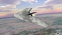
Here's a render result with mist and the "Mixing-Technique". You see, that you don't see shining the Background through. The first solution goes with the help of an external compositing program
and won't be explained in depth as we want to focus on how to solve
this issue within blender since it is open source.
::首先是使用外部编译程序,我们不会详细解释,因为我们只想在混合器中解决这个问题,因为它是开源的.Solution 1: Make use of an external composite software.
::解决方案1:使用外部复合软件.Just render your Background and your Objects separately with Alpha-Channels.
Then you import these files into a composite program on two layers.
(One for the Objects and one for the Background).
Between these layers you set a new "Color-Layer" with a solid greyish-blue color
(because this fits the color of the atmosphere) and create a clipping mask.
A "clipping mask" means that the "Color-Layer" is only visible where the objects of the top layer are.
And where there's no object you can see the Background.
As the object is partially transparent (because of Blender's Mist),
you will see the greyish-blue color shining through.
The more the object is away, the more transparent it is,
and the more the color-Layer will shine through the Objects.
::仅仅是用Alpha-Channels单独染你的背景和对象. 然后你将这些文件导入一个由两层组成的复合程序. 一层是对象,一层是背景. 在这些层之间,你设置一个新的"颜色层"以固体灰蓝色 (因为这与大气的颜色相匹配),并创建一个剪切面具. "剪切面具"意味着"颜色层"只能在顶层对象所在的地方可见. 而没有对象的地方,你可以看到背景. 由于对象是部分透明的 (由于混合器的雾),你会看到灰蓝色的颜色闪过. 越远的对象,越透明,颜色层会越多地闪过对象.Solution 2: Make use of Blender's Composite-Nodes.
::解决方案2:使用混合器的复合节点.Since Solution 1 seems not to be a big deal as we cannot afford expensive packages, we are also able
to achieve this "Mix-Technique" by Blender's built-in Composite-Nodes.
::由于解决方案1似乎不太重要,因为我们无法负担昂贵的包装,我们也可以通过Blender内置的复合节点实现这种"混合技术".To continue reading it would be good, if you know a little about Blender's Compositing-Nodes.
::如果您了解Blender的组合节点,Now, here's the interesting part of the tutorial, the Graph of the Nodes in the Node-Editor:
::现在,教程的有趣部分是节点编辑器中的节点图:
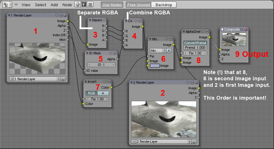
Description:
::描述:Step 1 Render Layer1
::步骤 1 染层1In the Render Settings Tab you assign the Objects which you don't want to be transparent to Render Layer1.
::在染设置选项卡中, 您将不希望透明的对象分配到染层1.See http://wiki.blender.org/index.php/Doc:Manual/Render/Layers for how to deal with RenderLayers.
::关于如何处理RenderLayers的方法,请参阅http://wiki.blender.org/index.php/Doc:Manual/Render/Layers.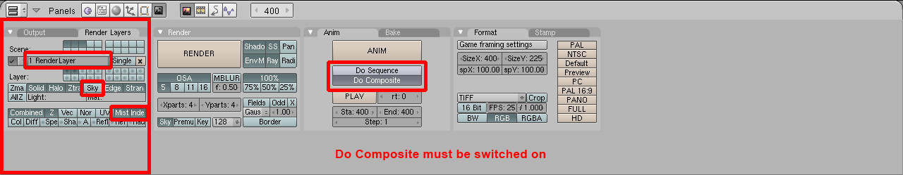
It is important that you turn off "Sky" and that you turn on "IndexPass". (The Option "Mist" delivers the same Value as the Alpha-Output in the Node RenderLayer1)
"IndexPass" will be explained in Step 5.
::关闭"Sky"并启动"IndexPass"非常重要. (选项"Mist"提供与Node RenderLayer1中的Alpha输出相同的值) "IndexPass"将在第5步中解释.Step 2 Render Layer2
::步骤 2 染层2This Layer renders only the Background, the Sky. In my case I had to enable other elements also, because otherwise the groundplane won't render.
I don' t know why, but this doesn't matter in our case.
::只有在我的情况下,我必须启用其他元素,因为否则地面平面不会染. 我不知道为什么,但这在我们的情况下并不重要.Step 3 Separating RGB+Alpha
::步骤3 分离RGB+AlphaThe "Image output" of the Node RenderLayer1 delivers RGB+A, that's a little distracting,
because you can see an Alpha-Output also. Select "Add" -> "Color" -> "Separate RGBA" in the Node-Editor Window.
::节点染层1的"图像输出"提供RGB+A,这有点分散注意力,因为你也可以看到Alpha输出. 在节点编辑器窗口中选择"添加" -> "颜色" -> "分离RGBA".Step 4 Combining RGBA
::第4步 结合RGBANow the Separated RGB gets combined again to RGB, but this time with a new Alpha of Step 5.
::现在,分离的RGB又被组合到RGB, 但这次是第5步的新Alpha.Step 5 Making the transparent Objects opaque
::步骤5 让透明的物体变得不透明The good thing is, that Blender's Object-ID Alpha Value does ignore mist.
So we can add an ID-Mask Node to get the Alpha of the Object into the new Image.
Here you must set the ID of the Object to the same number as in the ID-Mask Node.
Select the Object and set its ID Pass-Index!
Beside is a screenshot where you set the Object ID.
::好消息是,Blender的对象ID Alpha值确实忽略了mist.所以我们可以添加一个ID-Mask节点来将对象的Alpha输入新的图像.在这里,您必须将对象的ID设置为与ID-Mask节点相同的数字.选择对象并设置其ID Pass-Index!旁边是一个您设置对象ID的截图.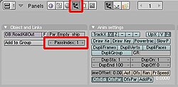
In the red marked section of the buttons window, you can set the ID of the object
Step 6 Mixing the Object with a Color
::第6步:将物体与颜色混合Here you add a Mix-Node to mix the Object with a "Horizon-Color".
The Color should be set to a bright greyish-blue as this is the color of the air inner the atmosphere.
Any color is possible, you may think of a dark red in a fire-hollow or of black if somewhere out in space.
::颜色应该设置为明亮的灰蓝色,因为这是大气内部的颜色.任何颜色都是可能的,你可能会想到火洞中的深红色或在太空中的黑色.Step 7 Setting the Factor of how much of the color should be added
::步骤7 设置颜色的添加量Blender delivers an Alpha-Value to the Objects due to the Mist.
If an object is far away or if the Mist-Intensity is very high,
the Alpha-Value of the Object decreases, which means the Alpha-Value becomes more black.
And if the Object is close, it has accordingly high Alpha, which means getting white.
Black means a Value of R-G-B 0-0-0 and White a Value of R-G-B 1-1-1.
::由于雾,混凝土将对象提供阿尔法值.如果一个物体远离或雾强度非常高,则对象的阿尔法值会下降,这意味着阿尔法值变得更黑.如果物体靠近,则相应地具有高阿尔法值,这意味着变白.黑色意味着R-G-B 0-0-0的值,白色意味着R-G-B 1-1-1的值.Since we want to use these values as a factor of how much to blend the Object
with our "Horizon-Color", we need to invert this Value.
::需要将这个值反转. 为了使这些值成为与"地平线颜色"的混合的因素,(Close Objects = High Alpha = Factor almost 1 - but we need Blend Factor close to 0, because we want low mist as the Object is close)
:So let's add an "Invert-Color-Node".
Get the Settings of the Node-Graph for this Node.
This Node inverts Black to white, dark-grey to bright grey, etc.
We now use this inverted alpha-value (or Mist-value)
as a factor for mixing the Horizon-Color with the Object.
::让我们添加一个"反转-颜色-节点". 获取这个节点的节点图的设置. 这个节点将黑色反转为白色,深灰色反转为明亮灰色等等. 我们现在将这个反转的alpha值 (或Mist值) 作为混合地平线颜色与对象的因素.Step 8 Layering the colored Objects over the Sky-Background
::步骤8 层次的彩色对象在天空背景Now you add an Alpha-Over-Node which will layer our Objects over the Sky-Background.
Be aware to use the settings shown in the screenshot and that the order of the two Image-Inputs
of the Alpha-Over-Node is very important.
The second Input always gets over the first Input.
::现在你添加一个Alpha-Over-Node,它将我们的Objects在天空背景上叠加.请注意使用屏幕截图中显示的设置,并且Alpha-Over-Node的两个图像-信息的顺序非常重要.第二个输入总是超过第一个输入.Step 9 Add an Output-Node
::步骤 9 添加一个输出节点Finally you need an Output-Node and to enable "Do Composite" in the RenderSettings.
::需要一个输出节点, 并在染设置中启用"Do Composite".Step 10 Example
::第十步示例Here an Example, of how it worked out in my project:
::让我们来看看我的项目是如何实现的:-
 Close Distance - Almost no Mist
::距离近 - - 几乎没有雾 -
 Far Distance - Low Mist or atmospheric opacity
::远距离 - 低雾或大气不透明 -
 Further Distance - (!)The Object is even scaled
::进一步的距离 - - 目标的尺寸是均的 -
 Farthermost Distance - In original size the Object would be so small that it isn't visible -only to make the Logic clear
::远距离 - 在原始尺寸的物体将是如此之小,它是不可见的 - 只是为了使逻辑清楚
Summary
::简要介绍Be sure, you got every step right - then all will work out properly.
What is almost of more importance, that you understood the logic behind this,
so that you learn about Blender's Compositing-Nodes and the 01-Logic ;)
::确保你每一步都做得对 - - 然后一切都会正常运行.Since "Mist" means something like "Bullsh**" in German I did not believe that it really
is like that in Blender - and it isn't! Blender is a quite nice and powerful tool.
And I hope that it'll ever be Open-Source.
::由于"Mist"在德语中意味着"Bullsh**",我不相信Blender真的会这样 - - 而事实并非如此! Blender是一个非常好而强大的工具.
-

 . To make sure that you have a regular tetrahedron, you can check the lengths of the edges (in Edit Mode, press N to open the Properties panel and locate the checkbox
Length
in the section
Edge Info
).
. To make sure that you have a regular tetrahedron, you can check the lengths of the edges (in Edit Mode, press N to open the Properties panel and locate the checkbox
Length
in the section
Edge Info
).
 , with
 being the edge length of the icosahedron (1.05 if made by the method above)